If you're seeing this message, it means we're having trouble loading external resources on our website.
If you're behind a web filter, please make sure that the domains *.kastatic.org and *.kasandbox.org are unblocked.
To log in and use all the features of Khan Academy, please enable JavaScript in your browser.

Chemistry library
Course: chemistry library > unit 9.
- States of matter
- States of matter follow-up
- Specific heat and latent heat of fusion and vaporization
- Specific heat, heat of fusion and vaporization example
- Chilling water problem
- Change of state example
- Vapor pressure
Phase diagrams
- Representing solids, liquids, and gases using particulate models
- Crystalline and amorphous polymers
- Representing alloys using particulate models
- Structure of metals and alloys
- Solids, liquids, and gases
Want to join the conversation?
- Upvote Button navigates to signup page
- Downvote Button navigates to signup page
- Flag Button navigates to signup page

Video transcript
Chemistry Learner
It's all about chemistry.
- Chemical Bonds
- Chemical Reactions
- Materials Chemistry
- Organic Chemistry
- Periodic Trends
- Periodic Table Groups
- How to Read Periodic Table
- Naming Covalent Compounds Worksheets
- Net Ionic Equation Worksheets
- Types of Chemical Reactions Worksheets
- Word Equations Worksheets
- Valence Electrons Worksheets
- Graphing Periodic Trends Worksheets
- Periodic Trends Ionization Energy Worksheets
- Atomic Structure And Isotopes Worksheets
Phase Diagram
How to read a phase diagram, phase diagram example.
A phase diagram represents the various physical states or phases of matter at different pressures and temperatures. In other words, it summarizes the effect of pressure and temperature on the nature of a substance. A phase diagram is divided into three areas representing the substances’ solid, liquid, and gaseous phases [1-4] .
Several distinct lines separate these phases. These lines are called lines of equilibrium or phase boundaries and represent the equilibrium between the phases. A point on these lines indicates that multiple phases can coexist in thermodynamic equilibrium. Phase transitions occur along these lines.
A representative phase diagram of a pure substance is shown below.
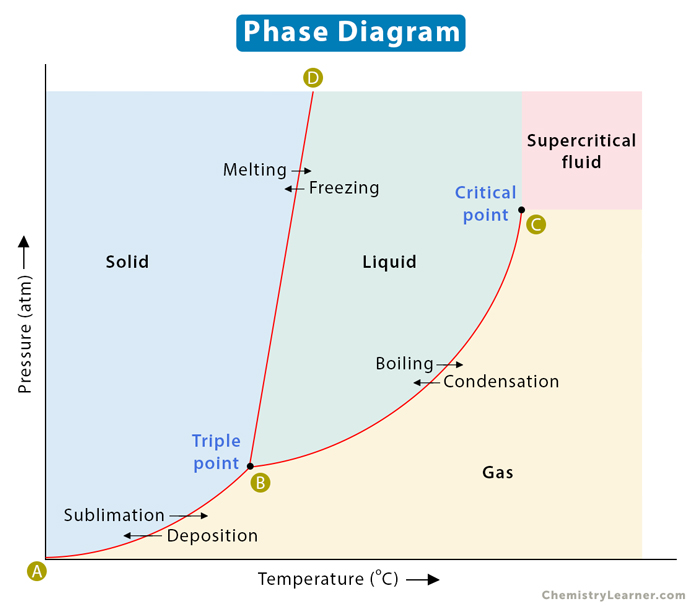
A two-dimensional phase diagram shows temperature along the horizontal axis and pressure along the vertical axis. The pressure is plotted in the unit of atmosphere (atm) or Pascal (Pa), and the temperature is in Kelvin (K) or degrees Celcius ( o C). The lines of equilibrium represent a pressure-temperature combination where two phases can coexist in equilibrium. Low temperature and high pressure favor solid formation, and high temperature and low pressure favor gas formation. Liquid lies in between these two regions [1-6] .
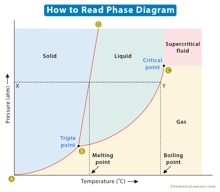
Consider the horizontal dashed line XY as shown in the image below. As we move across the diagram from left to right, we pass through all three phases of matter. We start with the solid phase, cross the solid-liquid line (BD), and move into the liquid phase. We continue along the dashed line, cross the liquid-vapor line (BC), and finally reach the gaseous phase. In summary, if we increase the temperature of a substance at constant pressure, the substance transforms from solid to liquid to gas.
Along any line, two phases are in equilibrium with one another. It means that the rate at which a substance transforms from one phase to another is the same as when it transforms back to the first phase. Let us now analyze these phase boundaries.
Consider line AB, where the solid phase is in equilibrium with its gaseous counterpart. Every point on this line represents the condition under which the solid is in equilibrium with the gas. In other words, the rate at which the solid transforms into gas is the same as when the gas transforms back into solid.
The BC line contains all the conditions of pressure and temperature at which the liquid boils. Here, the liquid is in equilibrium with the gas. In other words, the boiling rate is equal to the condensation rate.
The BD line represents the equilibrium between solid and liquid. Each point on this line depicts the condition under which a solid melts into a liquid. The reverse also holds. The rate of melting is equal to the rate of freezing. The BD line is normally vertical for most pure substances because the melting point is not much affected by a change in pressure. For most compounds, the slope is slightly positive. It is slightly negative for water because ice melts upon applying pressure.
Triple Point and Critical Point
The phase diagram has two essential points – triple point and critical point. The point where the lines intersect is called the triple point. It is the pressure and temperature conditions at which all three phases, solid, liquid, and gas, coexist in equilibrium.
The critical point is the highest temperature and pressure at which a gas and a liquid can coexist at equilibrium. The critical point terminates the liquid-gas line and establishes the critical pressure and temperature. Beyond this point, the two phases become indistinguishable and form a phase known as a supercritical fluid. In the image above, point B is the triple point, and point C is the critical point. The supercritical fluid phase is indicated distinctly.
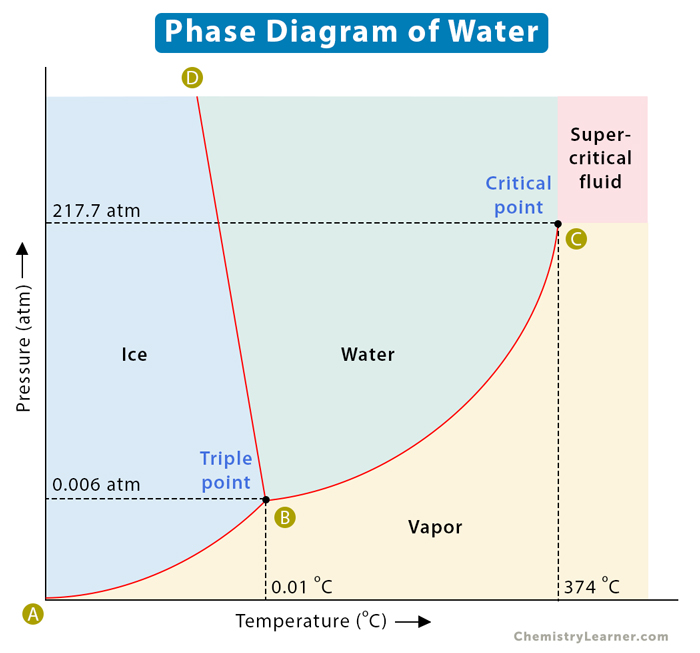
A well-known example of a phase diagram is that of water , as shown below. We know that water exists as ice, liquid water, and water vapor or steam. Water has a triple point corresponding to the temperature and pressure at which ice, liquid water, and vapor coexist in a stable equilibrium. It also has a critical point. It is that point at which water vapor cannot be forced back into water, no matter how much pressure is applied. Another example of a phase diagram is that of carbon dioxide, which is discussed in this article [1-6] .
The following table lists their values.
- Chem.libretexts.org
- Chemed.chem.purdue.edu
- Chemistrytalk.org
- Chemguide.co.uk
- Pressbooks-dev.oer.hawaii.edu
- Thoughtco.com
Related Articles

Sublimation

Graham’s Law

Crystal Field Theory

Van der Waals Equation
Leave a Reply Cancel reply
Your email address will not be published. Required fields are marked *
Trending Topics
© 2024 ( Chemistry Learner )
10.4 Phase Diagrams
Learning objectives.
By the end of this section, you will be able to:
- Explain the construction and use of a typical phase diagram
- Use phase diagrams to identify stable phases at given temperatures and pressures, and to describe phase transitions resulting from changes in these properties
- Describe the supercritical fluid phase of matter
In the previous module, the variation of a liquid’s equilibrium vapor pressure with temperature was described. Considering the definition of boiling point, plots of vapor pressure versus temperature represent how the boiling point of the liquid varies with pressure. Also described was the use of heating and cooling curves to determine a substance’s melting (or freezing) point. Making such measurements over a wide range of pressures yields data that may be presented graphically as a phase diagram. A phase diagram combines plots of pressure versus temperature for the liquid-gas, solid-liquid, and solid-gas phase-transition equilibria of a substance. These diagrams indicate the physical states that exist under specific conditions of pressure and temperature, and also provide the pressure dependence of the phase-transition temperatures (melting points, sublimation points, boiling points). A typical phase diagram for a pure substance is shown in Figure 10.30 .
To illustrate the utility of these plots, consider the phase diagram for water shown in Figure 10.31 .
We can use the phase diagram to identify the physical state of a sample of water under specified conditions of pressure and temperature. For example, a pressure of 50 kPa and a temperature of −10 °C correspond to the region of the diagram labeled “ice.” Under these conditions, water exists only as a solid (ice). A pressure of 50 kPa and a temperature of 50 °C correspond to the “water” region—here, water exists only as a liquid. At 25 kPa and 200 °C, water exists only in the gaseous state. Note that on the H 2 O phase diagram, the pressure and temperature axes are not drawn to a constant scale in order to permit the illustration of several important features as described here.
The curve BC in Figure 10.31 is the plot of vapor pressure versus temperature as described in the previous module of this chapter. This “liquid-vapor” curve separates the liquid and gaseous regions of the phase diagram and provides the boiling point for water at any pressure. For example, at 1 atm, the boiling point is 100 °C. Notice that the liquid-vapor curve terminates at a temperature of 374 °C and a pressure of 218 atm, indicating that water cannot exist as a liquid above this temperature, regardless of the pressure. The physical properties of water under these conditions are intermediate between those of its liquid and gaseous phases. This unique state of matter is called a supercritical fluid, a topic that will be described in the next section of this module.
The solid-vapor curve, labeled AB in Figure 10.31 , indicates the temperatures and pressures at which ice and water vapor are in equilibrium. These temperature-pressure data pairs correspond to the sublimation, or deposition, points for water. If we could zoom in on the solid-gas line in Figure 10.31 , we would see that ice has a vapor pressure of about 0.20 kPa at −10 °C. Thus, if we place a frozen sample in a vacuum with a pressure less than 0.20 kPa, ice will sublime. This is the basis for the “freeze-drying” process often used to preserve foods, such as the ice cream shown in Figure 10.32 .
The solid-liquid curve labeled BD shows the temperatures and pressures at which ice and liquid water are in equilibrium, representing the melting/freezing points for water. Note that this curve exhibits a slight negative slope (greatly exaggerated for clarity), indicating that the melting point for water decreases slightly as pressure increases. Water is an unusual substance in this regard, as most substances exhibit an increase in melting point with increasing pressure. This behavior is partly responsible for the movement of glaciers, like the one shown in Figure 10.33 . The bottom of a glacier experiences an immense pressure due to its weight that can melt some of the ice, forming a layer of liquid water on which the glacier may more easily slide.
The point of intersection of all three curves is labeled B in Figure 10.31 . At the pressure and temperature represented by this point, three phases of water coexist in equilibrium. This temperature-pressure data pair is called the triple point . At pressures lower than the triple point, water cannot exist as a liquid, regardless of the temperature.
Example 10.11
Determining the state of water.
(a) −10 °C and 50 kPa
(b) 25 °C and 90 kPa
(c) 50 °C and 40 kPa
(d) 80 °C and 5 kPa
(e) −10 °C and 0.3 kPa
(f) 50 °C and 0.3 kPa
Check Your Learning
At 0.3 kPa: s ⟶ g s ⟶ g at −58 °C. At 50 kPa: s ⟶ l s ⟶ l at 0 °C, l ⟶ g at 78 °C
Consider the phase diagram for carbon dioxide shown in Figure 10.34 as another example. The solid-liquid curve exhibits a positive slope, indicating that the melting point for CO 2 increases with pressure as it does for most substances (water being a notable exception as described previously). Notice that the triple point is well above 1 atm, indicating that carbon dioxide cannot exist as a liquid under ambient pressure conditions. Instead, cooling gaseous carbon dioxide at 1 atm results in its deposition into the solid state. Likewise, solid carbon dioxide does not melt at 1 atm pressure but instead sublimes to yield gaseous CO 2 . Finally, notice that the critical point for carbon dioxide is observed at a relatively modest temperature and pressure in comparison to water.
Example 10.12
Determining the state of carbon dioxide.
(a) −30 °C and 2000 kPa
(b) −90 °C and 1000 kPa
(c) −60 °C and 100 kPa
(d) −40 °C and 1500 kPa
(e) 0 °C and 100 kPa
(f) 20 °C and 100 kPa
at 1500 kPa: s ⟶ l s ⟶ l at −55 °C, l ⟶ g l ⟶ g at −10 °C;
at 50 kPa: s ⟶ g s ⟶ g at −60 °C
Supercritical Fluids
If we place a sample of water in a sealed container at 25 °C, remove the air, and let the vaporization-condensation equilibrium establish itself, we are left with a mixture of liquid water and water vapor at a pressure of 0.03 atm. A distinct boundary between the more dense liquid and the less dense gas is clearly observed. As we increase the temperature, the pressure of the water vapor increases, as described by the liquid-gas curve in the phase diagram for water ( Figure 10.31 ), and a two-phase equilibrium of liquid and gaseous phases remains. At a temperature of 374 °C, the vapor pressure has risen to 218 atm, and any further increase in temperature results in the disappearance of the boundary between liquid and vapor phases. All of the water in the container is now present in a single phase whose physical properties are intermediate between those of the gaseous and liquid states. This phase of matter is called a supercritical fluid , and the temperature and pressure above which this phase exists is the critical point ( Figure 10.35 ). Above its critical temperature, a gas cannot be liquefied no matter how much pressure is applied. The pressure required to liquefy a gas at its critical temperature is called the critical pressure. The critical temperatures and critical pressures of some common substances are given in the following table.
Link to Learning
Observe the liquid-to-supercritical fluid transition for carbon dioxide.
Like a gas, a supercritical fluid will expand and fill a container, but its density is much greater than typical gas densities, typically being close to those for liquids. Similar to liquids, these fluids are capable of dissolving nonvolatile solutes. They exhibit essentially no surface tension and very low viscosities, however, so they can more effectively penetrate very small openings in a solid mixture and remove soluble components. These properties make supercritical fluids extremely useful solvents for a wide range of applications. For example, supercritical carbon dioxide has become a very popular solvent in the food industry, being used to decaffeinate coffee, remove fats from potato chips, and extract flavor and fragrance compounds from citrus oils. It is nontoxic, relatively inexpensive, and not considered to be a pollutant. After use, the CO 2 can be easily recovered by reducing the pressure and collecting the resulting gas.
Example 10.13
The critical temperature of carbon dioxide.
The critical temperature of ammonia is 405.5 K, which is higher than room temperature. The critical temperature of oxygen is below room temperature; thus oxygen cannot be liquefied at room temperature.
Chemistry in Everyday Life
Decaffeinating coffee using supercritical co 2.
Coffee is the world’s second most widely traded commodity, following only petroleum. Across the globe, people love coffee’s aroma and taste. Many of us also depend on one component of coffee—caffeine—to help us get going in the morning or stay alert in the afternoon. But late in the day, coffee’s stimulant effect can keep you from sleeping, so you may choose to drink decaffeinated coffee in the evening.
Since the early 1900s, many methods have been used to decaffeinate coffee. All have advantages and disadvantages, and all depend on the physical and chemical properties of caffeine. Because caffeine is a somewhat polar molecule, it dissolves well in water, a polar liquid. However, since many of the other 400-plus compounds that contribute to coffee’s taste and aroma also dissolve in H 2 O, hot water decaffeination processes can also remove some of these compounds, adversely affecting the smell and taste of the decaffeinated coffee. Dichloromethane (CH 2 Cl 2 ) and ethyl acetate (CH 3 CO 2 C 2 H 5 ) have similar polarity to caffeine, and are therefore very effective solvents for caffeine extraction, but both also remove some flavor and aroma components, and their use requires long extraction and cleanup times. Because both of these solvents are toxic, health concerns have been raised regarding the effect of residual solvent remaining in the decaffeinated coffee.
Supercritical fluid extraction using carbon dioxide is now being widely used as a more effective and environmentally friendly decaffeination method ( Figure 10.36 ). At temperatures above 304.2 K and pressures above 7376 kPa, CO 2 is a supercritical fluid, with properties of both gas and liquid. Like a gas, it penetrates deep into the coffee beans; like a liquid, it effectively dissolves certain substances. Supercritical carbon dioxide extraction of steamed coffee beans removes 97−99% of the caffeine, leaving coffee’s flavor and aroma compounds intact. Because CO 2 is a gas under standard conditions, its removal from the extracted coffee beans is easily accomplished, as is the recovery of the caffeine from the extract. The caffeine recovered from coffee beans via this process is a valuable product that can be used subsequently as an additive to other foods or drugs.
As an Amazon Associate we earn from qualifying purchases.
This book may not be used in the training of large language models or otherwise be ingested into large language models or generative AI offerings without OpenStax's permission.
Want to cite, share, or modify this book? This book uses the Creative Commons Attribution License and you must attribute OpenStax.
Access for free at https://openstax.org/books/chemistry-2e/pages/1-introduction
- Authors: Paul Flowers, Klaus Theopold, Richard Langley, William R. Robinson, PhD
- Publisher/website: OpenStax
- Book title: Chemistry 2e
- Publication date: Feb 14, 2019
- Location: Houston, Texas
- Book URL: https://openstax.org/books/chemistry-2e/pages/1-introduction
- Section URL: https://openstax.org/books/chemistry-2e/pages/10-4-phase-diagrams
© Jan 8, 2024 OpenStax. Textbook content produced by OpenStax is licensed under a Creative Commons Attribution License . The OpenStax name, OpenStax logo, OpenStax book covers, OpenStax CNX name, and OpenStax CNX logo are not subject to the Creative Commons license and may not be reproduced without the prior and express written consent of Rice University.
Phase Diagrams

Core Concept
In this tutorial, you will learn about the major features of phase diagrams , also called phase change diagrams , as well as other types of diagrams, and how to interpret and understand their importance.
Topics Covered in Other Articles
- States of Matter
- What is Pressure?
- Properties of solids, liquids, gases
- Intermolecular Forces
- Physical vs. Chemical Properties
- Heat of Fusion
- Condensation – when a substance goes from gaseous to liquid state
- Vaporization – when a substance goes from liquid to gaseous state
- Fusion – when a substance goes from liquid to solid state
- Melting – when a substance goes from solid to liquid state
- Sublimation – when the substance goes directly from solid to gaseous state
- Deposition – when a substance goes directly from gaseous to solid state
- Phase Change – when a substance changes from one state of matter to another (e.g. solid to liquid, or liquid to gas)
What are Phase Chase Diagrams?
A phase transition occurs when a substance changes from one state of matter to another state. There are three primary states of matter : liquid, solid, and gas.
A phase diagram is a plot that illustrates the different phases of a substance across multiple variables, most often temperature and pressure. The diagram can help to demonstrate how changing these variables affects the state of matter of a particular substance.
Pressure-Temperature Phase Diagram
The pressure-temperature phase diagram is the most common and basic type.

A phase diagram of the type shown above plots pressure (in atmospheres) versus temperature (in degrees Celsius or Kelvin). The solid lines represent the phase boundaries, also called “coexistence curves,” because there are two phases coexisting in equilibrium with one another. The blue line shows the boiling point, or transition between liquid and gaseous state, the green line shows the freezing point, or transition between liquid and solid state, and the red line shows the conditions where a solid state can be converted directly to gaseous phase and vice versa.
Phase Diagram Descriptions
Here are some common words and phrases you will hear when learning about phase change diagrams.
Fusion (melting or freezing) curve – the curve that shows the transition between liquid and solid states
Vaporization (or condensation) curve – the curve that shows the transition between gaseous and liquid states
Sublimation (or deposition) curve – the curve that shows the transition between gaseous and solid states
Triple point – the point of temperature and pressure at which gas, liquid, and solid coexist in equilibrium
Critical point – the point of temperature and pressure at which the substance is indistinguishable between liquid and gaseous states
Phase boundary – the line that indicates the conditions under which two states of matter coexist in equilibrium
The Special Case of Water
A special case that is commonly discussed is the phase diagram of water. In the diagram from above, the dotted green line represents the solid-liquid coexistence curve in the phase diagram of water.
We can see that for the average substance, raising the pressure of the liquid will cause it to cross the curve and become a solid. However, for water, raising the pressure of the solid (ice) may cause it to cross the curve and become a liquid. This behavior is a consequence of the low density of the crystal structure of ice, which contains a large amount of free space due to hydrogen bonding .

Other Types of Phase Chase Diagrams
The pressure-temperature phase diagram is not the only type. There are many thermodynamic variables that can influence the phase behavior of a substance, including volume, entropy, enthalpy, and chemical potential. You can use any of these variables to generate a phase diagram showing for what values of two variables a sample is solid, liquid, or gaseous.
Since a two-dimensional diagram can only show two variables as axes, sometimes a third variable will be shown by way curves showing where this variable is constant. They have different names depending on the variable they represent. For example, an isobar shows constant pressure, an isochor constant volume, and an isotherm constant temperature.
3D Phase Diagrams
Three-dimensional phase change diagrams plot three thermodynamic variables and show regions of space corresponding to different phases. In this type of diagram, we have a triple line instead of a triple point, and coexistence surfaces instead of coexistence curves. Below is a generic 3D diagram plotting temperature, pressure, and specific volume.

Binary Mixtures
Binary mixtures have phase diagrams plotted against composition, usually represented as mole fraction of one component. This shows how the phase behavior of the mixture depends on the specific makeup of the sample. One of the most important characteristics of this type of plot is the eutectic point , which is the point on the diagram where the melting point is lowest, and usually falls somewhere in the middle. On the diagram below, you can find the eutectic point at about 40 mol % ammonium nitrate.
Crystals and Polymorphs
Crystalline solids can have multiple possible structures, dependent on thermodynamic variables. This is why you may hear someone talk about different forms of ice, such as ice II, ice III, or ice IV. You may also see multiple minerals with the same chemical formula, such as calcite and aragonite, which are also different crystalline phases (polymorphs) of the same substance. In cases like this, it is common to see a phase diagram with many phases, all of which are solid.
Further Reading – Phase Change Diagrams
Neat science trick: Instantly freeze water (On Susan Koch’s blog)
- Percent Yield
- Common Ion Effect
- Valence Electrons
- Newman Projections
- Colligative Properties
- Bond Enthalpy
- Clausius Clapeyron Equation

Want to create or adapt books like this? Learn more about how Pressbooks supports open publishing practices.
Private: Chapter Ten
Phase Diagrams (10.4)
By the end of this section, you will be able to:
- Explain the construction and use of a typical phase diagram
- Use phase diagrams to identify stable phases at given temperatures and pressures, and to describe phase transitions resulting from changes in these properties
- Describe the supercritical fluid phase of matter
In the previous module, the variation of a liquid’s equilibrium vapor pressure with temperature was described. Considering the definition of boiling point, plots of vapor pressure versus temperature represent how the boiling point of the liquid varies with pressure. Also described was the use of heating and cooling curves to determine a substance’s melting (or freezing) point. Making such measurements over a wide range of pressures yields data that may be presented graphically as a phase diagram. A phase diagram combines plots of pressure versus temperature for the liquid-gas, solid-liquid, and solid-gas phase-transition equilibria of a substance. These diagrams indicate the physical states that exist under specific conditions of pressure and temperature, and also provide the pressure dependence of the phase-transition temperatures (melting points, sublimation points, boiling points). A typical phase diagram for a pure substance is shown in Figure 10.32 .

To illustrate the utility of these plots, consider the phase diagram for water shown in Figure 10.33 .

We can use the phase diagram to identify the physical state of a sample of water under specified conditions of pressure and temperature. For example, a pressure of 50 kPa and a temperature of −10 °C correspond to the region of the diagram labeled “ice.” Under these conditions, water exists only as a solid (ice). A pressure of 50 kPa and a temperature of 50 °C correspond to the “water” region—here, water exists only as a liquid. At 25 kPa and 200 °C, water exists only in the gaseous state. Note that on the H 2 O phase diagram, the pressure and temperature axes are not drawn to a constant scale in order to permit the illustration of several important features as described here.
The curve BC in Figure 10.33 is the plot of vapor pressure versus temperature as described in the previous module of this chapter. This “liquid-vapor” curve separates the liquid and gaseous regions of the phase diagram and provides the boiling point for water at any pressure. For example, at 1 atm, the boiling point is 100 °C. Notice that the liquid- vapor curve terminates at a temperature of 374 °C and a pressure of 218 atm, indicating that water cannot exist as a liquid above this temperature, regardless of the pressure. The physical properties of water under these conditions are intermediate between those of its liquid and gaseous phases. This unique state of matter is called a supercritical fluid, a topic that will be described in the next section of this module.
The solid-vapor curve, labeled AB in Figure 10.33 , indicates the temperatures and pressures at which ice and water vapor are in equilibrium. These temperature-pressure data pairs correspond to the sublimation, or deposition, points for water. If we could zoom in on the solid-gas line in Figure 10.33 , we would see that ice has a vapor pressure of about 0.20 kPa at −10 °C. Thus, if we place a frozen sample in a vacuum with a pressure less than 0.20 kPa, ice will sublime. This is the basis for the “freeze-drying” process often used to preserve foods, such as the ice cream shown in Figure 10.34 .

The solid-liquid curve labeled BD shows the temperatures and pressures at which ice and liquid water are in equilibrium, representing the melting/freezing points for water. Note that this curve exhibits a slight negative slope (greatly exaggerated for clarity), indicating that the melting point for water decreases slightly as pressure increases. Water is an unusual substance in this regard, as most substances exhibit an increase in melting point with increasing pressure. This behavior is partly responsible for the movement of glaciers, like the one shown in Figure 10.35 . The bottom of a glacier experiences an immense pressure due to its weight that can melt some of the ice, forming a layer of liquid water on which the glacier may more easily slide.

The point of intersection of all three curves is labeled B in Figure 10.33 . At the pressure and temperature represented by this point, all three phases of water coexist in equilibrium. This temperature-pressure data pair is called the triple point . At pressures lower than the triple point, water cannot exist as a liquid, regardless of the temperature.
EXAMPLE 10.11
Determining the state of water.
Using the phase diagram for water given in Figure 10.33 , determine the state of water at the following temperatures and pressures:
(a) −10 °C and 50 kPa
(b) 25 °C and 90 kPa
(c) 50 °C and 40 kPa
(d) 80 °C and 5 kPa
(e) −10 °C and 0.3 kPa
(f) 50 °C and 0.3 kPa
Solution Using the phase diagram for water, we can determine that the state of water at each temperature and pressure given are as follows: (a) solid; (b) liquid; (c) liquid; (d) gas; (e) solid; (f) gas.
Check Your Learning What phase changes can water undergo as the temperature changes if the pressure is held at 0.3 kPa? If the pressure is held at 50 kPa?
At 0.3 kPa: s ⟶ g
s ⟶ g at −58 °C. At 50 kPa: s ⟶ l
s ⟶ l at 0 °C, l ⟶ g at 78 °C
Consider the phase diagram for carbon dioxide shown in Figure 10.36 as another example. The solid-liquid curve exhibits a positive slope, indicating that the melting point for CO 2 increases with pressure as it does for most substances (water being a notable exception as described previously). Notice that the triple point is well above 1 atm, indicating that carbon dioxide cannot exist as a liquid under ambient pressure conditions. Instead, cooling gaseous carbon dioxide at 1 atm results in its deposition into the solid state. Likewise, solid carbon dioxide does not melt at 1 atm pressure but instead sublimes to yield gaseous CO 2 . Finally, notice that the critical point for carbon dioxide is
observed at a relatively modest temperature and pressure in comparison to water.

Example 10.12
Determining the state of carbon dioxide.
Using the phase diagram for carbon dioxide shown in Figure 10.36 , determine the state of CO 2 at the following temperatures and pressures:
- −30 °C and 2000 kPa
- −60 °C and 1000 kPa
- −60 °C and 100 kPa
- −40 °C and 1500 kPa
- 0 °C and 100 kPa
- 20 °C and 100 kPa
Using the phase diagram for carbon dioxide provided, we can determine that the state of CO 2 at each temperature and pressure given are as follows: (a) liquid; (b) solid; (c) gas; (d) liquid; (e) gas; (f) gas.
Check Your Learning
Identify the phase changes that carbon dioxide will undergo as its temperature is increased from −100 °C while holding its pressure constant at 1500 kPa. At 50 kPa. At what approximate temperatures do these phase changes occur?
Answer: at 1500 kPa: s ⟶ l at −55 °C, l ⟶ g at −10 °C; at 500 kPa: s ⟶ g at −60 °C
Supercritical Fluids
If we place a sample of water in a sealed container at 25 °C, remove the air, and let the vaporization-condensation equilibrium establish itself, we are left with a mixture of liquid water and water vapor at a pressure of 0.03 atm.
A distinct boundary between the more dense liquid and the less dense gas is clearly observed. As we increase the temperature, the pressure of the water vapor increases, as described by the liquid-gas curve in the phase diagram for water ( Figure 10.33 ), and a two-phase equilibrium of liquid and gaseous phases remains. At a temperature of 374
°C, the vapor pressure has risen to 218 atm, and any further increase in temperature results in the disappearance of the boundary between liquid and vapor phases. All of the water in the container is now present in a single phase whose physical properties are intermediate between those of the gaseous and liquid states. This phase of matter is called a supercritical fluid , and the temperature and pressure above which this phase exists is the critical point ( Figure 10.37 ). Above its critical temperature, a gas cannot be liquefied no matter how much pressure is applied. The pressure required to liquefy a gas at its critical temperature is called the critical pressure. The critical temperatures and critical pressures of some common substances are given in the following table.

Link to LearningObserve the liquid-to-supercritical fluid transition (http://openstaxcollege.org/l/16supercrit) forcarbon dioxide.
Like a gas, a supercritical fluid will expand and fill a container, but its density is much greater than typical gas densities, typically being close to those for liquids. Similar to liquids, these fluids are capable of dissolving nonvolatile solutes. They exhibit essentially no surface tension and very low viscosities, however, so they can more
The Critical Temperature of Carbon DioxideIf we shake a carbon dioxide fire extinguisher on a cool day (18 °C), we can hear liquid CO2 sloshing around inside the cylinder. However, the same cylinder appears to contain no liquid on a hot summer day (35 °C). Explain these observations.SolutionOn the cool day, the temperature of the CO2 is below the critical temperature of CO2, 304 K or 31 °C (Table 10.3), so liquid CO2 is present in the cylinder. On the hot day, the temperature of the CO2 is greater than its critical temperature of 31 °C. Above this temperature no amount of pressure can liquefy CO2 so no liquid CO2 exists in the fire extinguisher.Check Your LearningAmmonia can be liquefied by compression at room temperature; oxygen cannot be liquefied under these conditions. Why do the two gases exhibit different behavior?Answer: The critical temperature of ammonia is 405.5 K, which is higher than room temperature. The critical temperature of oxygen is below room temperature; thus oxygen cannot be liquefied at roomtemperature.
Chemistry in Everyday Life
Decaffeinating coffee using supercritical co 2.
Coffee is the world’s second most widely traded commodity, following only petroleum. Across the globe, people love coffee’s aroma and taste. Many of us also depend on one component of coffee—caffeine—to help us get going in the morning or stay alert in the afternoon. But late in the day, coffee’s stimulant effect can keep you from sleeping, so you may choose to drink decaffeinated coffee in the evening.
Since the early 1900s, many methods have been used to decaffeinate coffee. All have advantages and disadvantages, and all depend on the physical and chemical properties of caffeine. Because caffeine is a somewhat polar molecule, it dissolves well in water, a polar liquid. However, since many of the other 400-plus compounds that contribute to coffee’s taste and aroma also dissolve in H 2 O, hot water decaffeination processes can also remove some of these compounds, adversely affecting the smell and taste of the decaffeinated coffee. Dichloromethane (CH 2 Cl 2 ) and ethyl acetate (CH 3 CO 2 C 2 H 5 ) have similar polarity to caffeine, and are therefore very effective solvents for caffeine extraction, but both also remove some flavor and aroma components, and their use requires long extraction and cleanup times. Because both of these solvents are toxic, health concerns have been raised regarding the effect of residual solvent remaining in the decaffeinated coffee.
Supercritical fluid extraction using carbon dioxide is now being widely used as a more effective and environmentally friendly decaffeination method ( Figure 10.38 ). At temperatures above 304.2 K and pressures above 7376 kPa, CO 2 is a supercritical fluid, with properties of both gas and liquid. Like a gas, it penetrates deep into the coffee beans; like a liquid, it effectively dissolves certain substances. Supercritical carbon dioxide extraction of steamed coffee beans removes 97−99% of the caffeine, leaving coffee’s flavor and aroma compounds intact. Because CO 2 is a gas under standard conditions, its removal from the extracted coffee beans is easily accomplished, as is the recovery of the caffeine from the extract. The caffeine recovered from coffee beans via this process is a valuable product that can be used subsequently as an additive to other foods or drugs.

Chemistry 110 Copyright © by OpenStax is licensed under a Creative Commons Attribution 4.0 International License , except where otherwise noted.
Share This Book

Want to create or adapt books like this? Learn more about how Pressbooks supports open publishing practices.
60 Phase Diagrams
Learning Objectives
By the end of this section, you will be able to:
- Explain the construction and use of a typical phase diagram
- Use phase diagrams to identify stable phases at given temperatures and pressures, and to describe phase transitions resulting from changes in these properties
- Describe the supercritical fluid phase of matter
In the previous module, the variation of a liquid’s equilibrium vapor pressure with temperature was described. Considering the definition of boiling point, plots of vapor pressure versus temperature represent how the boiling point of the liquid varies with pressure. Also described was the use of heating and cooling curves to determine a substance’s melting (or freezing) point. Making such measurements over a wide range of pressures yields data that may be presented graphically as a phase diagram. A phase diagram combines plots of pressure versus temperature for the liquid-gas, solid-liquid, and solid-gas phase-transition equilibria of a substance. These diagrams indicate the physical states that exist under specific conditions of pressure and temperature, and also provide the pressure dependence of the phase-transition temperatures (melting points, sublimation points, boiling points). A typical phase diagram for a pure substance is shown in (Figure) .

To illustrate the utility of these plots, consider the phase diagram for water shown in (Figure) .

We can use the phase diagram to identify the physical state of a sample of water under specified conditions of pressure and temperature. For example, a pressure of 50 kPa and a temperature of −10 °C correspond to the region of the diagram labeled “ice.” Under these conditions, water exists only as a solid (ice). A pressure of 50 kPa and a temperature of 50 °C correspond to the “water” region—here, water exists only as a liquid. At 25 kPa and 200 °C, water exists only in the gaseous state. Note that on the H 2 O phase diagram, the pressure and temperature axes are not drawn to a constant scale in order to permit the illustration of several important features as described here.
The curve BC in (Figure) is the plot of vapor pressure versus temperature as described in the previous module of this chapter. This “liquid-vapor” curve separates the liquid and gaseous regions of the phase diagram and provides the boiling point for water at any pressure. For example, at 1 atm, the boiling point is 100 °C. Notice that the liquid-vapor curve terminates at a temperature of 374 °C and a pressure of 218 atm, indicating that water cannot exist as a liquid above this temperature, regardless of the pressure. The physical properties of water under these conditions are intermediate between those of its liquid and gaseous phases. This unique state of matter is called a supercritical fluid, a topic that will be described in the next section of this module.
The solid-vapor curve, labeled AB in (Figure) , indicates the temperatures and pressures at which ice and water vapor are in equilibrium. These temperature-pressure data pairs correspond to the sublimation, or deposition, points for water. If we could zoom in on the solid-gas line in (Figure) , we would see that ice has a vapor pressure of about 0.20 kPa at −10 °C. Thus, if we place a frozen sample in a vacuum with a pressure less than 0.20 kPa, ice will sublime. This is the basis for the “freeze-drying” process often used to preserve foods, such as the ice cream shown in (Figure) .

The solid-liquid curve labeled BD shows the temperatures and pressures at which ice and liquid water are in equilibrium, representing the melting/freezing points for water. Note that this curve exhibits a slight negative slope (greatly exaggerated for clarity), indicating that the melting point for water decreases slightly as pressure increases. Water is an unusual substance in this regard, as most substances exhibit an increase in melting point with increasing pressure. This behavior is partly responsible for the movement of glaciers, like the one shown in (Figure) . The bottom of a glacier experiences an immense pressure due to its weight that can melt some of the ice, forming a layer of liquid water on which the glacier may more easily slide.

The point of intersection of all three curves is labeled B in (Figure) . At the pressure and temperature represented by this point, all three phases of water coexist in equilibrium. This temperature-pressure data pair is called the triple point . At pressures lower than the triple point, water cannot exist as a liquid, regardless of the temperature.
Determining the State of Water
Using the phase diagram for water given in (Figure) , determine the state of water at the following temperatures and pressures:
(a) −10 °C and 50 kPa
(b) 25 °C and 90 kPa
(c) 50 °C and 40 kPa
(d) 80 °C and 5 kPa
(e) −10 °C and 0.3 kPa
(f) 50 °C and 0.3 kPa
Using the phase diagram for water, we can determine that the state of water at each temperature and pressure given are as follows: (a) solid; (b) liquid; (c) liquid; (d) gas; (e) solid; (f) gas.
Check Your Learning
What phase changes can water undergo as the temperature changes if the pressure is held at 0.3 kPa? If the pressure is held at 50 kPa?

Consider the phase diagram for carbon dioxide shown in (Figure) as another example. The solid-liquid curve exhibits a positive slope, indicating that the melting point for CO 2 increases with pressure as it does for most substances (water being a notable exception as described previously). Notice that the triple point is well above 1 atm, indicating that carbon dioxide cannot exist as a liquid under ambient pressure conditions. Instead, cooling gaseous carbon dioxide at 1 atm results in its deposition into the solid state. Likewise, solid carbon dioxide does not melt at 1 atm pressure but instead sublimes to yield gaseous CO 2 . Finally, notice that the critical point for carbon dioxide is observed at a relatively modest temperature and pressure in comparison to water.

Determining the State of Carbon Dioxide
Using the phase diagram for carbon dioxide shown in (Figure) , determine the state of CO 2 at the following temperatures and pressures:
(a) −30 °C and 2000 kPa
(b) −60 °C and 1000 kPa
(c) −60 °C and 100 kPa
(d) −40 °C and 1500 kPa
(e) 0 °C and 100 kPa
(f) 20 °C and 100 kPa
Using the phase diagram for carbon dioxide provided, we can determine that the state of CO 2 at each temperature and pressure given are as follows: (a) liquid; (b) solid; (c) gas; (d) liquid; (e) gas; (f) gas.
Identify the phase changes that carbon dioxide will undergo as its temperature is increased from −100 °C while holding its pressure constant at 1500 kPa. At 50 kPa. At what approximate temperatures do these phase changes occur?

Supercritical Fluids
If we place a sample of water in a sealed container at 25 °C, remove the air, and let the vaporization-condensation equilibrium establish itself, we are left with a mixture of liquid water and water vapor at a pressure of 0.03 atm. A distinct boundary between the more dense liquid and the less dense gas is clearly observed. As we increase the temperature, the pressure of the water vapor increases, as described by the liquid-gas curve in the phase diagram for water ( (Figure) ), and a two-phase equilibrium of liquid and gaseous phases remains. At a temperature of 374 °C, the vapor pressure has risen to 218 atm, and any further increase in temperature results in the disappearance of the boundary between liquid and vapor phases. All of the water in the container is now present in a single phase whose physical properties are intermediate between those of the gaseous and liquid states. This phase of matter is called a supercritical fluid , and the temperature and pressure above which this phase exists is the critical point ( (Figure) ). Above its critical temperature, a gas cannot be liquefied no matter how much pressure is applied. The pressure required to liquefy a gas at its critical temperature is called the critical pressure. The critical temperatures and critical pressures of some common substances are given in the following table.

Observe the liquid-to-supercritical fluid transition for carbon dioxide.
Like a gas, a supercritical fluid will expand and fill a container, but its density is much greater than typical gas densities, typically being close to those for liquids. Similar to liquids, these fluids are capable of dissolving nonvolatile solutes. They exhibit essentially no surface tension and very low viscosities, however, so they can more effectively penetrate very small openings in a solid mixture and remove soluble components. These properties make supercritical fluids extremely useful solvents for a wide range of applications. For example, supercritical carbon dioxide has become a very popular solvent in the food industry, being used to decaffeinate coffee, remove fats from potato chips, and extract flavor and fragrance compounds from citrus oils. It is nontoxic, relatively inexpensive, and not considered to be a pollutant. After use, the CO 2 can be easily recovered by reducing the pressure and collecting the resulting gas.
The Critical Temperature of Carbon Dioxide
If we shake a carbon dioxide fire extinguisher on a cool day (18 °C), we can hear liquid CO 2 sloshing around inside the cylinder. However, the same cylinder appears to contain no liquid on a hot summer day (35 °C). Explain these observations.
On the cool day, the temperature of the CO 2 is below the critical temperature of CO 2 , 304 K or 31 °C ( (Figure) ), so liquid CO 2 is present in the cylinder. On the hot day, the temperature of the CO 2 is greater than its critical temperature of 31 °C. Above this temperature no amount of pressure can liquefy CO 2 so no liquid CO 2 exists in the fire extinguisher.
Ammonia can be liquefied by compression at room temperature; oxygen cannot be liquefied under these conditions. Why do the two gases exhibit different behavior?
Coffee is the world’s second most widely traded commodity, following only petroleum. Across the globe, people love coffee’s aroma and taste. Many of us also depend on one component of coffee—caffeine—to help us get going in the morning or stay alert in the afternoon. But late in the day, coffee’s stimulant effect can keep you from sleeping, so you may choose to drink decaffeinated coffee in the evening.
Since the early 1900s, many methods have been used to decaffeinate coffee. All have advantages and disadvantages, and all depend on the physical and chemical properties of caffeine. Because caffeine is a somewhat polar molecule, it dissolves well in water, a polar liquid. However, since many of the other 400-plus compounds that contribute to coffee’s taste and aroma also dissolve in H 2 O, hot water decaffeination processes can also remove some of these compounds, adversely affecting the smell and taste of the decaffeinated coffee. Dichloromethane (CH 2 Cl 2 ) and ethyl acetate (CH 3 CO 2 C 2 H 5 ) have similar polarity to caffeine, and are therefore very effective solvents for caffeine extraction, but both also remove some flavor and aroma components, and their use requires long extraction and cleanup times. Because both of these solvents are toxic, health concerns have been raised regarding the effect of residual solvent remaining in the decaffeinated coffee.
Supercritical fluid extraction using carbon dioxide is now being widely used as a more effective and environmentally friendly decaffeination method ( (Figure) ). At temperatures above 304.2 K and pressures above 7376 kPa, CO 2 is a supercritical fluid, with properties of both gas and liquid. Like a gas, it penetrates deep into the coffee beans; like a liquid, it effectively dissolves certain substances. Supercritical carbon dioxide extraction of steamed coffee beans removes 97−99% of the caffeine, leaving coffee’s flavor and aroma compounds intact. Because CO 2 is a gas under standard conditions, its removal from the extracted coffee beans is easily accomplished, as is the recovery of the caffeine from the extract. The caffeine recovered from coffee beans via this process is a valuable product that can be used subsequently as an additive to other foods or drugs.

Key Concepts and Summary
The temperature and pressure conditions at which a substance exists in solid, liquid, and gaseous states are summarized in a phase diagram for that substance. Phase diagrams are combined plots of three pressure-temperature equilibrium curves: solid-liquid, liquid-gas, and solid-gas. These curves represent the relationships between phase-transition temperatures and pressures. The point of intersection of all three curves represents the substance’s triple point—the temperature and pressure at which all three phases are in equilibrium. At pressures below the triple point, a substance cannot exist in the liquid state, regardless of its temperature. The terminus of the liquid-gas curve represents the substance’s critical point, the pressure and temperature above which a liquid phase cannot exist.
Chemistry End of Chapter Exercises
Instructions
Complete the following exercises by providing answers to each question. There are a total of 6 questions in this section. Please be aware that certain questions may contain subsections.
1. From the phase diagram for water ( (Figure) ), determine the state of water at:
(a) 35 °C and 85 kPa
(b) −15 °C and 40 kPa
(c) −15 °C and 0.1 kPa
(d) 75 °C and 3 kPa
(e) 40 °C and 0.1 kPa
(f) 60 °C and 50 kPa
2. What phase changes will take place when water is subjected to varying pressure at a constant temperature of 0.005 °C? At 40 °C? At −40 °C?
Answer(s): At low pressures and 0.005 °C, the water is a gas. As the pressure increases to 4.6 torr, the water becomes a solid; as the pressure increases still more, it becomes a liquid. At 40 °C, water at low pressure is a vapor; at pressures higher than about 75 torr, it converts into a liquid. At −40 °C, water goes from a gas to a solid as the pressure increases above very low values.
3. Pressure cookers allow food to cook faster because the higher pressure inside the pressure cooker increases the boiling temperature of water. A particular pressure cooker has a safety valve that is set to vent steam if the pressure exceeds 3.4 atm. What is the approximate maximum temperature that can be reached inside this pressure cooker? Explain your reasoning.
4. From the phase diagram for carbon dioxide in (Figure) , determine the state of CO 2 at:
(a) 20 °C and 1000 kPa
(b) 10 °C and 2000 kPa
(c) 10 °C and 100 kPa
(d) −40 °C and 500 kPa
(e) −80 °C and 1500 kPa
(f) −80 °C and 10 kPa
Answer(s): (a) gas; (b) gas; (c) gas; (d) gas; (e) solid; (f) gas
5. Determine the phase changes that carbon dioxide undergoes as pressure is increased at a constant temperature of (a) −50 °C and (b) 50 °C. If the temperature is held at −40 °C? At 20 °C? (See the phase diagram in (Figure) .)
6. Consider a cylinder containing a mixture of liquid carbon dioxide in equilibrium with gaseous carbon dioxide at an initial pressure of 65 atm and a temperature of 20 °C. Sketch a plot depicting the change in the cylinder pressure with time as gaseous carbon dioxide is released at constant temperature.

7. Dry ice, CO 2 ( s ), does not melt at atmospheric pressure. It sublimes at a temperature of −78 °C. What is the lowest pressure at which CO 2 ( s ) will melt to give CO 2 ( l )? At approximately what temperature will this occur? (See (Figure) for the phase diagram.)
8. If a severe storm results in the loss of electricity, it may be necessary to use a clothesline to dry laundry. In many parts of the country in the dead of winter, the clothes will quickly freeze when they are hung on the line. If it does not snow, will they dry anyway? Explain your answer.
Answer(s): Yes, ice will sublime, although it may take it several days. Ice has a small vapor pressure, and some ice molecules form gas and escape from the ice crystals. As time passes, more and more solid converts to gas until eventually the clothes are dry.
9. Is it possible to liquefy nitrogen at room temperature (about 25 °C)? Is it possible to liquefy sulfur dioxide at room temperature? Explain your answers.
10. Elemental carbon has one gas phase, one liquid phase, and two different solid phases, as shown in the phase diagram:

(a) On the phase diagram, label the gas and liquid regions.
(b) Graphite is the most stable phase of carbon at normal conditions. On the phase diagram, label the graphite phase.
(c) If graphite at normal conditions is heated to 2500 K while the pressure is increased to 10 10 Pa, it is converted into diamond. Label the diamond phase.
(d) Circle each triple point on the phase diagram.
(e) In what phase does carbon exist at 5000 K and 10 8 Pa?
(f) If the temperature of a sample of carbon increases from 3000 K to 5000 K at a constant pressure of 10 6 Pa, which phase transition occurs, if any?

(e) liquid phase (f) sublimation
Chemistry 2e 2019 Copyright © 2018 by OSCRiceUniversity is licensed under a Creative Commons Attribution 4.0 International License , except where otherwise noted.
Share This Book
Just added to your cart

Chemistry Homework: Reading the Phase Diagram
Adding product to your cart
- Practice reading a phase diagram
- Identify and define the triple point and critical point on a phase diagram
- Relate temperature, energy, and pressure to phases changes
- Understand the concepts of phases of matter and how they relate to energy
- A good understanding of phase changes related to energy changes, changes in attractive forces, and particle movement and arrangement
- Choosing a selection results in a full page refresh.
- Press the space key then arrow keys to make a selection.
Browse Course Material
Course info.
- Prof. Donald Sadoway
Departments
- Materials Science and Engineering
As Taught In
- Chemical Engineering
Learning Resource Types
Introduction to solid state chemistry, 33. unary phase diagrams.
« Previous | Next »
Session Overview
Prerequisites.
Before starting this session, you should be familiar with:
- The Bonding and Molecules module, in particular Session 12: Intermolecular Forces
Looking Ahead
This is the first of three sessions on solid solutions and phase diagrams. Proceed to the next session, Session 34 .
Learning Objectives
After completing this session, you should be able to:
- Summarize the purpose of a phase diagram.
- Give a detailed interpretation of the phase diagram of water.
- Given a set of material properties data, draw the phase diagram.
- Given a phase diagram, describe some properties of the material, e.g. the relative densities of its solid and liquid forms.
Archived Lecture Notes #10 (PDF) , Part A
Lecture Video
- Download video
- Download transcript
Lecture Slides (PDF - 3.0MB)
Lecture Summary
Phase stability is the basis for the solid state of matter. Knowledge of phase stability enables applications like:
- conducting failure analysis – recognizing phase “signatures” in the material
- cooking at altitude – adapting to different pressure/temperature relationships
- automobile engine cooling – exploiting pressure and chemical composition to control the coolant’s boiling point (a phase transition temperature)
Prof. Sadoway introduces phase diagrams as “stability maps” and “archives of pressure/temperature relationships.”
This lecture defines and gives examples of phase , one phase and two phase systems, equilibrium, component, and triple point . A detailed discussion of the most familiar one phase system, water, is followed by comparisons of the phase diagrams of aluminum and silicon.
Prof. Sadoway does some live demonstrations for the class:
- various objects are immersed in liquid nitrogen, going below their glass transition temperature
- properties of liquid oxygen
- sublimation of solid frozen CO 2 , aka ‘dry ice’
The phase diagram of zirconia illustrates the concept of changing a material’s composition to produce desired behaviors at particular temperature/pressure conditions. The phase diagram of carbon illustrates how artificial diamonds are made. Bisumth and sulfur phase diagrams – “phase diagrams from hell” – have many regions . Returning to water, Prof. Sadoway discusses the unusual phases of ice at very high pressures and very low temperatures.
As a final application note, the lecture ends with a quick summary of coffee decaffeination as a process employing sophisticated manipulation of phase transitions.
Problems (PDF)
Solutions (PDF)
More phase diagram homework problems will be provided for the next two sessions.
For Further Study
Queen. “‘Under Pressure’ (Live at Wembley).” June 16, 2009. YouTube. Accessed November 18, 2010. http://www.youtube.com/watch?v=SJCTgtDU-74 .
Alexander Calder, Mercury Fountain , 1937. Fundació Joan Miró. Barcelona, Spain.
Other OCW and OER Content

You are leaving MIT OpenCourseWare
phase diagram
All Formats
Resource types, all resource types.
- Rating Count
- Price (Ascending)
- Price (Descending)
- Most Recent
Phase diagram

Phase Changes, Phase Diagrams , & Heating/Cooling Curves

2nd/3rd/4th/5th Phases of The Moon Diagram - Labeling and Coloring or Cookies

Phase Diagram Activity Stations

Moon Phases Diagram | Science Graphic Organizer Template

- Easel Activity

Phase Change Diagram Activity - ( phase change & triple point) - 24 stations

Moon Phases Worksheet- Activity- Diagramming the Phases of the Moon

Chemistry: Reading the Phase Diagram Doodle Notes

Time Temperature Graphs and Phase Diagrams Chemistry Doodle Diagrams

Lesson Plan: Phase Diagrams

Solar Eclipse Clip Art - Solar Eclipse Phases , Diagrams , and Pinhole Viewers

Chemistry Homework: Reading the Phase Diagram

Mitosis Hands On Station Activity and Cell Cycle Worksheet with Phases Diagrams

Phase Change Diagrams 20 Questions for Google Classroom & Distance Learning

- Google Forms™
- Internet Activities

Phase Diagram Card Sort
Drawing The Cell Cycle Activity - Phases of Mitosis and Diagrams + Notes

Interpreting Phase Diagrams and Heating Curves

Phase Diagrams Notes

DIAGRAM Moon Phases - Rotation and Revolution - 5th Grade Science

- Google Apps™

Mitosis Phases Bundle with Diagrams , Games & Worksheets for Stages of Mitosis

CELL CYCLE & MITOSIS GAME ACTIVITY with mitosis phase diagrams

Phases of Matter & Diagrams : 8-Resource Hybrid Bundle Lesson Plan ~Distance L

Oreo Moon Phases Diagram

Space - Moon Phases Diagram Sheet

Lunar Phase Diagrams and Worksheets

- We're hiring
- Help & FAQ
- Privacy policy
- Student privacy
- Terms of service
- Tell us what you think
- Planet Earth
- Strange News
How To Read Phase Diagrams Chemistry
Table of Contents:
phase diagrams of pure substances . An explanation of how to interpret the phase diagrams for pure substances including carbon dioxide and water.
The phase diagram shows that the water would first freeze to form ice as it crossed into the solid area. When the pressure fell low enough, the ice would then sublime to give water vapour. In other words, the change is from liquid to solid to vapour. I find that satisfyingly bizarre!
Video advice: Phase diagrams
Understanding and interpreting phase diagrams

There are various guide-lines that you can use if you want to. For example, if the substance is commonly a liquid at or around room temperature, you tend to call what comes away from it a vapour. A slightly wider use would be to call it a vapour if the substance is below its critical point, and a gas if it is above it. Certainly it would be unusual to call anything a vapour if it was above its critical point at room temperature – oxygen or nitrogen or hydrogen, for example. These would all be described as gases.
Phase Diagrams
T.B. Massalski, D.E. Laughlin, in Reference Module in Materials Science and Materials Engineering, 2022.
- Publisher Summary
- Phase diagram:
- Viscosity measurement:
- Fluorescence measurement:
- Membrane dialysis:
Phase DiagramsT. B. Massalski, D.E. Laughlin, in Reference Module in Materials Science and Materials Engineering, 20177 Phase DiagramsPhase diagrams are graphical plots that are devised to show the relationships between the various phases that appear within the system under equilibrium conditions. As such, the diagrams are variously called constitutional diagrams, equilibrium diagrams, or phase diagrams. A single-component phase diagram can be simply a one- or two-dimensional plot, showing the phase changes in the given component (e. g., in iron) as temperature and/or pressure changes. Most diagrams, however, are two-dimensional plots describing the phase relationships in systems made up of two of more components. These usually contain fields (areas) consisting of multiple phase fields, as well as single-phase fields. Some typical examples are shown below. Read full chapterURL: sciencedirect. com/science/article/pii/B9780128035818032422Phase diagramsKLAUS HACK, in The SGTE Casebook (Second Edition), 2008Publisher SummaryThis chapter discusses a phase diagram, which is derivable from a projection of a property diagram.
Interpreting Phase Diagrams
- Learning Objective
Phase diagrams illustrate the effects selected variables of a system have on the state of matter. Phase diagrams are divided into three single phase regions that cover the pressure-temperature space over which the matter being evaluated exists: liquid, gaseous, and solid states. The lines that separate these single phase regions are known as phase boundaries. Along the phase boundaries, the matter being evaluated exists simultaneously in equilibrium between the two states that border the phase boundary.
33. Unary Phase Diagrams
This page contains materials for the solid solutions class session on unary phase diagrams. It features a 1-hour lecture video, and also presents the prerequisites, learning objectives, reading assignment, lecture slides, homework with solutions, and resources for further study.
- Prerequisites
- Looking Ahead
- Learning Objectives
- Lecture Summary
- Other OCW and OER Content
For Further Study
« Previous | Next » Session Overview Modules Solid Solutions Concepts introduction to phase diagrams, basic definitions of phase, component, and equilibrium, one-component phase diagrams Keywords stability, pressure, temperature, vapor, liquid, solid, phase, equilibrium, component, triple point, melting, boiling, glass transition temperature, polymorph, sublimation, supercritical Chemical Substances water (H2O), zirconia (ZrO2), snowflake obsidian, aluminum (Al), silicon (Si), carbon dioxide (CO2), nitrogen (N), bismuth (Bi), sulfur (S), oxygen (O), argon (Ar), “dry ice”, carbon (C), mercury (Hg) Applications failure analysis, cooking food at altitude and in pressure cooker, automobile engine cooling, ice skating, artificial diamonds, coffee decaffeination Prerequisites Before starting this session, you should be familiar with: The Bonding and Molecules module, in particular Session 12: Intermolecular Forces Looking Ahead This is the first of three sessions on solid solutions and phase diagrams.
How do you read phase diagrams?
Correctly…. Let us look at a phase diagram of WATER and see if we make some sense from it….typically pressure is plotted against temperature….and we can read the resultant phase given the two coordinates. The scale of the x and y axes, representing temperature, and pressure respectively are fairly arbitrary….but they are useful. We see under conditions of high pressure we get a condensed phase, whereas under conditions of low pressure, and high temperature a gas is favoured. At P=218*atm and T=374*K we reach the critical point…and importantly at this point the densities of the water phase, and the gaseous phase become equal and we can no longer distinguish between the two phases, hence beyond this there is no designation of phase. At lower temperatures, say at 100 “”^@C liquid water expresses a vapour pressure of 1*atm…and thus we define the normal boiling point of water. At high pressures, and low temperatures we typically encounter a solid, and the graph reflects this. At much lower pressures, we find the triple point, the conditions of temperature and pressure at which ALL three phases are in equilibrium… Of special significance for the water molecule is that the SLOPE of the line differentiating the solid phase, and the liquid phase is NEGATIVE. This is very unusual….but we need further information from the Clapeyron equation to determine its significance….to put it in a nutshell, this means that the density of the solid phase is LESS than the density of the liquid phase, and so ice-bergs float…. Anyway, we are flying blind a bit here. If there is a specific issue or query raise it, and someone will address it. I would also consult your text for its account of phase diagrams.
The size from the #x# and #y# axes, representing temperature, and pressure correspondingly are fairly arbitrary.
Video advice: Chemistry Lecture: Phase Diagrams
http://mcatforme.com

A temperature‐pressure graph showing the various states of matter is a phase diagram. Phase refers to a single homogeneous physical state. Different phases have either different compositions or different physical states. In the preceding figure, there are three phases with the same composition in the solid, liquid, and gaseous states of matter.
Although the introductory example of H 2O mentioned changes of state caused by varying the temperature, it is known that variation of pressure can also produce such changes. In laboratory experiments, these two environmental factors—temperature and pressure—can each be varied or held constant; they are referred to as independent variables. Figure 1 assigns these variables to axes to form a plot that describes the physical condition at each point in the graph. The vertical axis is the pressure measured in atmospheres (atm).
Learn How To Read a Phase Diagram
A phase diagram is a graphical representation of pressure and temperature of a material. Learn about phase diagrams and how to read them.
A phase diagram is really a graphical representation of pressure and temperature of the material. Phase diagrams show the condition of matter at confirmed pressure and temperature. They reveal the limitations between phases and also the processes that occur once the pressure and/or temperatures are altered to mix these limitations. This short article outlines so what can be learned from the phase diagram and the way to read one.
Phases of Matter and Phase Diagrams
One of the properties of matter is its state. States of matter include solid, liquid or gas phases. At high pressures and low temperatures, the substance is in the solid phase. At low pressure and high temperature, the substance is in the gas phase. The liquid phase appears between the two regions. In this diagram, Point A is in the solid region. Point B is in the liquid phase and Point C is in the gas phase. The lines on a phase diagram correspond to the dividing lines between two phases. These lines are known as phase boundaries. At a point on a phase boundary, the substance can be in either one or the other phases that appear at either side of the boundary. These phases exist in equilibrium with one another. There are two points of interest on a phase diagram. Point D is the point where all three phases meet. When the material is at this pressure and temperature, it can exist in all three phases. This point is called the triple point. The other point of interest is when the pressure and temperature are high enough to be unable to tell the difference between the gas and liquid phases.
Phase diagram is a graphical representation of the physical states of a substance under different conditions of temperature and pressure. A typical phase diagram has pressure on the y-axis and temperature on the x-axis. As we cross the lines or curves on the phase diagram, a phase change occurs. In addition, two states of the substance coexist in equilibrium on the lines or curves.
Problems – Solid: A state of matter with tightly packed particles which do not change the shape or volume of the container that it is in. However, this does not mean that the volume of a solid is a constant. Solids can expand and contract when temperatures change. This is why when you look up the density of a solid, it will indicate the temperature at which the value for density is listed. Solids have strong intermolecular forces that keep particles in close proximity to one another. Another interesting thing to think about is that all true solids have crystalline structures. This means that their particles are arranged in a three-dimensional, orderly pattern. Solids will undergo phase changes when they come across energy changes.
Phase Diagram
A phase diagram in physical chemistry, engineering, mineralogy, and materials science is a type of chart used to show conditions at which thermodynamically distinct phases can occur at equilibrium.
You are able to apply Le Chatelier’s Principle for this equilibrium just like whether it would be a chemical equilibrium. Should you boost the pressure, the equilibrium will move in a way regarding counter the modification you’ve just made. Whether it converted from liquid to solid, pressure would have a tendency to decrease again since the solid occupies slightly less space for many substances.
At its simplest, a phase can be just another term for solid, liquid or gas. If you have some ice floating in water, you have a solid phase present and a liquid phase. If there is air above the mixture, then that is another phase. But the term can be used more generally than this. For example, oil floating on water also consists of two phases – in this case, two liquid phases. If the oil and water are contained in a bucket, then the solid bucket is yet another phase. In fact, there might be more than one solid phase if the handle is attached separately to the bucket rather than moulded as a part of the bucket.
Consider a cylinder containing a mixture of liquid carbon dioxide in equilibrium with gaseous carbon dioxide at an initial pressure of 65 atm and a temperature of 20 °C. Sketch a plot depicting the change in the cylinder pressure with time as gaseous carbon dioxide is released at constant temperature.
Chemistry End of Chapter Exercises – In the previous module, the variation of a liquid’s equilibrium vapor pressure with temperature was described. Considering the definition of boiling point, plots of vapor pressure versus temperature represent how the boiling point of the liquid varies with pressure. Also described was the use of heating and cooling curves to determine a substance’s melting (or freezing) point. Making such measurements over a wide range of pressures yields data that may be presented graphically as a phase diagram. A phase diagram combines plots of pressure versus temperature for the liquid-gas, solid-liquid, and solid-gas phase-transition equilibria of a substance. These diagrams indicate the physical states that exist under specific conditions of pressure and temperature, and also provide the pressure dependence of the phase-transition temperatures (melting points, sublimation points, boiling points). A typical phase diagram for a pure substance is shown in (link).
The features of a phase change diagrams are thoroughly explained as well as its related terms and concepts, and the phase diagram of water.
- Phase Diagram Descriptions
- The Special Case of Water
- 3D Phase Diagrams
- Binary Mixtures
- Crystals and Polymorphs
What are Phase Chase Diagrams?
Core ConceptIn this tutorial, you will learn about the major features of phase diagrams, also called phase change diagrams, as well as other types of diagrams, and how to interpret and understand their importance. Topics Covered in Other ArticlesStates of MatterWhat is Pressure? Properties of solids, liquids, gasesIntermolecular ForcesPhysical vs. Chemical PropertiesVocabularyCondensation – when a substance goes from gaseous to liquid stateVaporization – when a substance goes from liquid to gaseous stateFusion – when a substance goes from liquid to solid stateMelting – when a substance goes from solid to liquid stateSublimation – when the substance goes directly from solid to gaseous stateDeposition – when a substance goes directly from gaseous to solid statePhase Change – when a substance changes from one state of matter to another (e. g. solid to liquid, or liquid to gas)What are Phase Chase Diagrams? A phase transition occurs when a substance changes from one state of matter to another state.
Video advice: Phase Diagrams of Water & CO2 Explained – Chemistry – Melting, Boiling & Critical Point
This chemistry video tutorial explains the concepts behind the phase diagram of CO2 / Carbon Dioxide and the phase diagram of water / H2O. This video contains plenty of examples and practice problems:

How do I read phase diagrams?
6:2012:47How to Read and Interpret Phase Diagrams - YouTubeYouTubeStart of suggested clipEnd of suggested clipSo the first one says label the phases. Notice that the phases are not labeled. So if I go down hereMoreSo the first one says label the phases. Notice that the phases are not labeled. So if I go down here I only have two phases that you would transition from it to go to a point where horizontally.
What can you determine from a phase diagram?
A phase diagram is a graph which shows under what conditions of temperature and pressure distinct phases of matter occur . The simplest phase diagrams are of pure substances. These diagrams plot pressure on the y-axis and temperature on the x-axis.
How do you read density on a phase diagram?
The phase which has the higher density is the phase which exists under higher pressure and lower temperature. Thus, in a phase diagram showing pressure as a function of temperature, look for the phase which lies in the upper left region . Usually the solid phase is the densest.
What does each line in a phase diagram represents?
The lines in a phase diagram represent boundaries between different phases ; at any combination of temperature and pressure that lies on a line, two phases are in equilibrium.
How do you read an alloy phase diagram?
6:5823:25How to use phase diagrams and the lever rule to understand metal alloysYouTube.
Related Articles:
- How To Read Phase Diagrams Geology
- How To Read A Phase Diagram Geology
- How To Read A Ternary Phase Diagram Geology
- How To Draw Energy Level Diagrams Chemistry
- How To Read A Manometer Chemistry
- What Is Phase Rule In Chemistry

Science Journalist
Science atlas, our goal is to spark the curiosity that exists in all of us. We invite readers to visit us daily, explore topics of interest, and gain new perspectives along the way.
You may also like

What Jobs Can I Get With A Marine Science Degree

What Does Distal Versus Proximal Sections Geology Mean

What Is Evolution Definition Biology
Add comment, cancel reply.
Your email address will not be published. Required fields are marked *
Save my name, email, and website in this browser for the next time I comment.
Recent discoveries

When Walmart Invested In Bossa Nova Robotics

When Is The Innovation Curve Used

How To Apply Dr Earth Fertilizer

Why Is Data Science Mainly About Teamwork
- Animals 3041
- Astronomy 8
- Biology 2281
- Chemistry 482
- Culture 1333
- Health 8466
- History 2152
- Physics 913
- Planet Earth 3239
- Science 2158
- Strange News 1230
- Technology 3625
Random fact

Which Of The Following Are Correct Associations Quizlet Geology

Snapsolve any problem by taking a picture. Try it in the Numerade app?

- school Campus Bookshelves
- menu_book Bookshelves
- perm_media Learning Objects
- login Login
- how_to_reg Request Instructor Account
- hub Instructor Commons
Margin Size
- Download Page (PDF)
- Download Full Book (PDF)
- Periodic Table
- Physics Constants
- Scientific Calculator
- Reference & Cite
- Tools expand_more
- Readability
selected template will load here
This action is not available.
16.3: Phase Change Diagrams
- Last updated
- Save as PDF
- Page ID 465604
\( \newcommand{\vecs}[1]{\overset { \scriptstyle \rightharpoonup} {\mathbf{#1}} } \)
\( \newcommand{\vecd}[1]{\overset{-\!-\!\rightharpoonup}{\vphantom{a}\smash {#1}}} \)
\( \newcommand{\id}{\mathrm{id}}\) \( \newcommand{\Span}{\mathrm{span}}\)
( \newcommand{\kernel}{\mathrm{null}\,}\) \( \newcommand{\range}{\mathrm{range}\,}\)
\( \newcommand{\RealPart}{\mathrm{Re}}\) \( \newcommand{\ImaginaryPart}{\mathrm{Im}}\)
\( \newcommand{\Argument}{\mathrm{Arg}}\) \( \newcommand{\norm}[1]{\| #1 \|}\)
\( \newcommand{\inner}[2]{\langle #1, #2 \rangle}\)
\( \newcommand{\Span}{\mathrm{span}}\)
\( \newcommand{\id}{\mathrm{id}}\)
\( \newcommand{\kernel}{\mathrm{null}\,}\)
\( \newcommand{\range}{\mathrm{range}\,}\)
\( \newcommand{\RealPart}{\mathrm{Re}}\)
\( \newcommand{\ImaginaryPart}{\mathrm{Im}}\)
\( \newcommand{\Argument}{\mathrm{Arg}}\)
\( \newcommand{\norm}[1]{\| #1 \|}\)
\( \newcommand{\Span}{\mathrm{span}}\) \( \newcommand{\AA}{\unicode[.8,0]{x212B}}\)
\( \newcommand{\vectorA}[1]{\vec{#1}} % arrow\)
\( \newcommand{\vectorAt}[1]{\vec{\text{#1}}} % arrow\)
\( \newcommand{\vectorB}[1]{\overset { \scriptstyle \rightharpoonup} {\mathbf{#1}} } \)
\( \newcommand{\vectorC}[1]{\textbf{#1}} \)
\( \newcommand{\vectorD}[1]{\overrightarrow{#1}} \)
\( \newcommand{\vectorDt}[1]{\overrightarrow{\text{#1}}} \)
\( \newcommand{\vectE}[1]{\overset{-\!-\!\rightharpoonup}{\vphantom{a}\smash{\mathbf {#1}}}} \)
Freezing, condensation, and deposition, which are the reverse of fusion, sublimation, and vaporization—are exothermic. Thus heat pumps that use refrigerants are essentially air-conditioners running in reverse. Heat from the environment is used to vaporize the refrigerant, which is then condensed to a liquid in coils within a house to provide heat. The energy changes that occur during phase changes can be quantified by using a heating or cooling curve.
Heating Curves
Figure \(\PageIndex{3}\) shows a heating curve, a plot of temperature versus heating time, for a 75 g sample of water. The sample is initially ice at 1 atm and −23°C; as heat is added, the temperature of the ice increases linearly with time. The slope of the line depends on both the mass of the ice and the specific heat ( C s ) of ice, which is the number of joules required to raise the temperature of 1 g of ice by 1°C. As the temperature of the ice increases, the water molecules in the ice crystal absorb more and more energy and vibrate more vigorously. At the melting point, they have enough kinetic energy to overcome attractive forces and move with respect to one another. As more heat is added, the temperature of the system does not increase further but remains constant at 0°C until all the ice has melted. Once all the ice has been converted to liquid water, the temperature of the water again begins to increase. Now, however, the temperature increases more slowly than before because the specific heat capacity of water is greater than that of ice. When the temperature of the water reaches 100°C, the water begins to boil. Here, too, the temperature remains constant at 100°C until all the water has been converted to steam. At this point, the temperature again begins to rise, but at a faster rate than seen in the other phases because the heat capacity of steam is less than that of ice or water.

Thus the temperature of a system does not change during a phase change . In this example, as long as even a tiny amount of ice is present, the temperature of the system remains at 0°C during the melting process, and as long as even a small amount of liquid water is present, the temperature of the system remains at 100°C during the boiling process. The rate at which heat is added does not affect the temperature of the ice/water or water/steam mixture because the added heat is being used exclusively to overcome the attractive forces that hold the more condensed phase together. Many cooks think that food will cook faster if the heat is turned up higher so that the water boils more rapidly. Instead, the pot of water will boil to dryness sooner, but the temperature of the water does not depend on how vigorously it boils.
The temperature of a sample does not change during a phase change.
If heat is added at a constant rate, as in Figure \(\PageIndex{3}\), then the length of the horizontal lines, which represents the time during which the temperature does not change, is directly proportional to the magnitude of the enthalpies associated with the phase changes. In Figure \(\PageIndex{3}\), the horizontal line at 100°C is much longer than the line at 0°C because the enthalpy of vaporization of water is several times greater than the enthalpy of fusion.
A superheated liquid is a sample of a liquid at the temperature and pressure at which it should be a gas. Superheated liquids are not stable; the liquid will eventually boil, sometimes violently. The phenomenon of superheating causes “bumping” when a liquid is heated in the laboratory. When a test tube containing water is heated over a Bunsen burner, for example, one portion of the liquid can easily become too hot. When the superheated liquid converts to a gas, it can push or “bump” the rest of the liquid out of the test tube. Placing a stirring rod or a small piece of ceramic (a “boiling chip”) in the test tube allows bubbles of vapor to form on the surface of the object so the liquid boils instead of becoming superheated. Superheating is the reason a liquid heated in a smooth cup in a microwave oven may not boil until the cup is moved, when the motion of the cup allows bubbles to form.
Cooling Curves
The cooling curve, a plot of temperature versus cooling time, in Figure \(\PageIndex{4}\) plots temperature versus time as a 75 g sample of steam, initially at 1 atm and 200°C, is cooled. Although we might expect the cooling curve to be the mirror image of the heating curve in Figure \(\PageIndex{3}\), the cooling curve is not an identical mirror image. As heat is removed from the steam, the temperature falls until it reaches 100°C. At this temperature, the steam begins to condense to liquid water. No further temperature change occurs until all the steam is converted to the liquid; then the temperature again decreases as the water is cooled. We might expect to reach another plateau at 0°C, where the water is converted to ice; in reality, however, this does not always occur. Instead, the temperature often drops below the freezing point for some time, as shown by the little dip in the cooling curve below 0°C. This region corresponds to an unstable form of the liquid, a supercooled liquid. If the liquid is allowed to stand, if cooling is continued, or if a small crystal of the solid phase is added (a seed crystal), the supercooled liquid will convert to a solid, sometimes quite suddenly. As the water freezes, the temperature increases slightly due to the heat evolved during the freezing process and then holds constant at the melting point as the rest of the water freezes. Subsequently, the temperature of the ice decreases again as more heat is removed from the system.

Supercooling effects have a huge impact on Earth’s climate. For example, supercooling of water droplets in clouds can prevent the clouds from releasing precipitation over regions that are persistently arid as a result. Clouds consist of tiny droplets of water, which in principle should be dense enough to fall as rain. In fact, however, the droplets must aggregate to reach a certain size before they can fall to the ground. Usually a small particle (a nucleus ) is required for the droplets to aggregate; the nucleus can be a dust particle, an ice crystal, or a particle of silver iodide dispersed in a cloud during seeding (a method of inducing rain). Unfortunately, the small droplets of water generally remain as a supercooled liquid down to about −10°C, rather than freezing into ice crystals that are more suitable nuclei for raindrop formation. One approach to producing rainfall from an existing cloud is to cool the water droplets so that they crystallize to provide nuclei around which raindrops can grow. This is best done by dispersing small granules of solid CO 2 (dry ice) into the cloud from an airplane. Solid CO 2 sublimes directly to the gas at pressures of 1 atm or lower, and the enthalpy of sublimation is substantial (25.3 kJ/mol). As the CO 2 sublimes, it absorbs heat from the cloud, often with the desired results.
Example \(\PageIndex{1}\): Cooling Hot Tea
If a 50.0 g ice cube at 0.0°C is added to 500 mL of tea at 20.0°C, what is the temperature of the tea when the ice cube has just melted? Assume that no heat is transferred to or from the surroundings. The density of water (and iced tea) is 1.00 g/mL over the range 0°C–20°C, the specific heats of liquid water and ice are 4.184 J/(g•°C) and 2.062 J/(g•°C), respectively, and the enthalpy of fusion of ice is 6.01 kJ/mol.
Given: mass, volume, initial temperature, density, specific heats, and \(ΔH_{fus}\)
Asked for: final temperature
Substitute the values given into the general equation relating heat gained to heat lost (Equation 5.39) to obtain the final temperature of the mixture.
When two substances or objects at different temperatures are brought into contact, heat will flow from the warmer one to the cooler. The amount of heat that flows is given by
\[q=mC_sΔT\]
where q is heat, m is mass, C s is the specific heat, and Δ T is the temperature change. Eventually, the temperatures of the two substances will become equal at a value somewhere between their initial temperatures. Calculating the temperature of iced tea after adding an ice cube is slightly more complicated. The general equation relating heat gained and heat lost is still valid, but in this case we also have to take into account the amount of heat required to melt the ice cube from ice at 0.0°C to liquid water at 0.0°C.
Exercise \(\PageIndex{1}\): Death by Freezing
Suppose you are overtaken by a blizzard while ski touring and you take refuge in a tent. You are thirsty, but you forgot to bring liquid water. You have a choice of eating a few handfuls of snow (say 400 g) at −5.0°C immediately to quench your thirst or setting up your propane stove, melting the snow, and heating the water to body temperature before drinking it. You recall that the survival guide you leafed through at the hotel said something about not eating snow, but you cannot remember why—after all, it’s just frozen water. To understand the guide’s recommendation, calculate the amount of heat that your body will have to supply to bring 400 g of snow at −5.0°C to your body’s internal temperature of 37°C. Use the data in Example \(\PageIndex{1}\)
200 kJ (4.1 kJ to bring the ice from −5.0°C to 0.0°C, 133.6 kJ to melt the ice at 0.0°C, and 61.9 kJ to bring the water from 0.0°C to 37°C), which is energy that would not have been expended had you first melted the snow.
IMAGES
VIDEO
COMMENTS
As we increase the temperature, the pressure of the water vapor increases, as described by the liquid-gas curve in the phase diagram for water (Figure 10.5.2 10.5. 2 ), and a two-phase equilibrium of liquid and gaseous phases remains. At a temperature of 374 °C, the vapor pressure has risen to 218 atm, and any further increase in temperature ...
Phase diagram is a graphical representation of the physical states of a substance under different conditions of temperature and pressure. A typical phase diagram has pressure on the y-axis and temperature on the x-axis. As we cross the lines or curves on the phase diagram, a phase change occurs. In addition, two states of the substance coexist ...
With this homework page, students will practice reading a phase diagram. There are 3 different phase diagrams and 15 questions. A complete KEY is included. Objectives: Practice reading a phase diagram. Identify and define the triple point and critical point on a phase diagram. Relate temperature, energy, and pressure to phases changes.
This is another great question. In the video here, Sal uses a horizontal line through the phase diagram. But, it doesn't have to be horizontal. Imagine a vertical line through this diagram-- for water, choose 100 degrees C. As long as you are at 100 C, you can change the phase by changing the pressure on the system.
How to Read a Phase Diagram. A two-dimensional phase diagram shows temperature along the horizontal axis and pressure along the vertical axis. The pressure is plotted in the unit of atmosphere (atm) or Pascal (Pa), and the temperature is in Kelvin (K) or degrees Celcius ( o C). The lines of equilibrium represent a pressure-temperature combination where two phases can coexist in equilibrium.
The Phase Diagram of Water. Figure 11.7.2 shows the phase diagram of water and illustrates that the triple point of water occurs at 0.01°C and 0.00604 atm (4.59 mmHg). Far more reproducible than the melting point of ice, which depends on the amount of dissolved air and the atmospheric pressure, the triple point (273.16 K) is used to define the absolute (Kelvin) temperature scale.
As we increase the temperature, the pressure of the water vapor increases, as described by the liquid-gas curve in the phase diagram for water ( Figure 10.31 ), and a two-phase equilibrium of liquid and gaseous phases remains. At a temperature of 374 °C, the vapor pressure has risen to 218 atm, and any further increase in temperature results ...
We can use the phase diagram to identify the physical state of a sample of water under specified conditions of pressure and temperature. For example, a pressure of 50 kPa and a temperature of −10 °C correspond to the region of the diagram labeled "ice.". Under these conditions, water exists only as a solid (ice).
Three-dimensional phase change diagrams plot three thermodynamic variables and show regions of space corresponding to different phases. In this type of diagram, we have a triple line instead of a triple point, and coexistence surfaces instead of coexistence curves. Below is a generic 3D diagram plotting temperature, pressure, and specific volume.
Consider the phase diagram for carbon dioxide shown in Figure 10.36 as another example. The solid-liquid curve exhibits a positive slope, indicating that the melting point for CO 2 increases with pressure as it does for most substances (water being a notable exception as described previously). Notice that the triple point is well above 1 atm, indicating that carbon dioxide cannot exist as a ...
10. Elemental carbon has one gas phase, one liquid phase, and two different solid phases, as shown in the phase diagram: (a) On the phase diagram, label the gas and liquid regions. (b) Graphite is the most stable phase of carbon at normal conditions. On the phase diagram, label the graphite phase.
ONE-COMPONENT PHASE DIAGRAM. Figure 1 illustrates the temperatures and pressures at which water can exist as a solid, liquid or vapor. The curves represent the points at which two of the phases coexist in equilibrium. At the point Tt vapor, liquid and solid coexist in equilibrium. In the fields of the diagram (phase fields) only one phase exists.
This homework page is included in the lesson: Phase Changes, Phase Diagrams, & Heating/Cooling Curves. This homework page can be used for homework, class practice, or a quiz. With this homework page, students will practice reading a phase diagram. There are 3 different phase diagrams and 15 questions. A complete KE
A phase diagram is graph showing the conditions of temperature and pressure under which a substance exists in the solid, liquid, and gas phases. Examine the general phase diagram shown in Figure below. In each of the three colored regions of the diagram, the substance is in a single state (or phase). The dark lines that act as the boundary ...
This page contains materials for the solid solutions class session on unary phase diagrams. It features a 1-hour lecture video, and also presents the prerequisites, learning objectives, reading assignment, lecture slides, homework with solutions, and resources for further study.
This homework page can be used for homework, class practice, or a quiz.With this homework page, students will practice reading a phase diagram. There are 3 different phase diagrams and 15 questions.A complete KEY is included.Objectives: Practice reading a phase diagramIdentify and define the triple point and critical point on a phase ...
b. Build your understanding of phase diagrams, either via textbook or videos. Textbook reading options o Ashby Engineering Materials 2 Chapter 3 (Phase Diagrams 1) and Chapter 4 (Phase Diagrams 2) o Callister 6th - 9th editions: Chapter 9 (Phase Diagrams) HOMEWORK 7 SCI 1410: materials science & solid state chemistry .
Skills to Develop. Identify and describe the parts of a phase diagram. You know that phase changes usually depend on temperature, which determines the kinetic energy of atoms and molecules. We mentioned before that they also depend on pressure. In the section on phase changes we said that the boiling point is the place where vapor pressure is ...
A phase diagram in physical chemistry, engineering, mineralogy, and materials science is a type of chart used to show conditions at which thermodynamically distinct phases can occur at equilibrium. You are able to apply Le Chatelier's Principle for this equilibrium just like whether it would be a chemical equilibrium.
Thank you! â ¤ï¸ Reading the Phase Diagram Homework Reading the Phase Diagram Name: Period: Date: Color and label the three sections of the phase diagram for water. What is the boiling point at 100 atm pressure? ... Discover the Wonders of Chemistry: Your Introductory Guide. Atoms, Molecules, and Ions: Understanding the Building Blocks of ...
Figure 10.14.1 10.14. 1 The normal freezing point (a) and triple point (b) of water. The total pressure on the contents of this container is 1 atm (101.3 kPa) and its temperature is exactly 273.15 K (0.00°C). As far as liquid and solid are concerned, this corresponds to point F in the phase diagram. If we could now pump all the air out of the ...
It'll make us certain that we aren't doing your homework for you. Basically any question with the wording your question has is considered homework; it needn't be literally one. Self-study questions, puzzles etc. also count as homework. Don't worry, they're not banned. But, we require a minimal effort. Otherwise, this question may get closed.
Figure 16.3.1 16.3. 1: A Heating Curve for Water. This plot of temperature shows what happens to a 75 g sample of ice initially at 1 atm and −23°C as heat is added at a constant rate: A-B: heating solid ice; B-C: melting ice; C-D: heating liquid water; D-E: vaporizing water; E-F: heating steam. Thus the temperature of a system does ...