Subscribe or renew today
Every print subscription comes with full digital access

Science News
How fingerprints form was a mystery — until now.
A theory proposed by mathematician Alan Turing in the 1950s helps explain the process

Three of the most common fingerprint shapes — arch, loop and whorl (traced in purple) — can be explained in part by a theory proposed by British mathematician Alan Turing.
J. Glover et al / Cell 2023
Share this:
By McKenzie Prillaman
February 9, 2023 at 11:00 am
Scientists have finally figured out how those arches, loops and whorls formed on your fingertips.
While in the womb, fingerprint-defining ridges expand outward in waves starting from three different points on each fingertip. The raised skin arises in a striped pattern thanks to interactions between three molecules that follow what’s known as a Turing pattern, researchers report February 9 in Cell . How those ridges spread from their starting sites — and merge — determines the overarching fingerprint shape.
Fingerprints are unique and last for a lifetime. They’ve been used to identify individuals since the 1800s. Several theories have been put forth to explain how fingerprints form, including spontaneous skin folding, molecular signaling and the idea that ridge pattern may follow blood vessel arrangements.
Scientists knew that the ridges that characterize fingerprints begin to form as downward growths into the skin, like trenches. Over the few weeks that follow, the quickly multiplying cells in the trenches start growing upward, resulting in thickened bands of skin.
Since budding fingerprint ridges and developing hair follicles have similar downward structures, researchers in the new study compared cells from the two locations. The team found that both sites share some types of signaling molecules — messengers that transfer information between cells — including three known as WNT, EDAR and BMP. Further experiments revealed that WNT tells cells to multiply, forming ridges in the skin, and to produce EDAR, which in turn further boosts WNT activity. BMP thwarts these actions.
To examine how these signaling molecules might interact to form patterns, the team adjusted the molecules’ levels in mice. Mice don’t have fingerprints, but their toes have striped ridges in the skin comparable to human prints. “We turn a dial — or molecule — up and down, and we see the way the pattern changes,” says developmental biologist Denis Headon of the University of Edinburgh.
Increasing EDAR resulted in thicker, more spaced-out ridges, while decreasing it led to spots rather than stripes. The opposite occurred with BMP, since it hinders EDAR production.
That switch between stripes and spots is a signature change seen in systems governed by Turing reaction-diffusion, Headon says. This mathematical theory, proposed in the 1950s by British mathematician Alan Turing, describes how chemicals interact and spread to create patterns seen in nature ( SN: 7/2/10 ). Though, when tested, it explains only some patterns ( SN: 1/21/14 ).
Mouse digits, however, are too tiny to give rise to the elaborate shapes seen in human fingerprints. So, the researchers used computer models to simulate a Turing pattern spreading from the three previously known ridge initiation sites on the fingertip: the center of the finger pad, under the nail and at the joint’s crease nearest the fingertip.
By altering the relative timing, location and angle of these starting points, the team could create each of the three most common fingerprint patterns — arches, loops and whorls — and even rarer ones. Arches, for instance, can form when finger pad ridges get a slow start, allowing ridges originating from the crease and under the nail to occupy more space.
“It’s a very well-done study,” says developmental and stem cell biologist Sarah Millar, director of the Black Family Stem Cell Institute at the Icahn School of Medicine at Mount Sinai in New York City.
Controlled competition between molecules also determines hair follicle distribution, says Millar, who was not involved in the work. The new study, she says, “shows that the formation of fingerprints follows along some basic themes that have already been worked out for other types of patterns that we see in the skin.”
Millar notes that people with gene mutations that affect WNT and EDAR have skin abnormalities. “The idea that those molecules might be involved in fingerprint formation was floating around,” she says.
Overall, Headon says, the team aims to aid formation of skin structures, like sweat glands, when they’re not developing properly in the womb, and maybe even after birth.
“What we want to do, in broader terms, is understand how the skin matures.”
More Stories from Science News on Health & Medicine

Aimee Grant investigates the needs of autistic people

These windpipe cells trigger coughs to keep water out of the lungs

What can period blood reveal about a person’s health?

Teens are using an unregulated form of THC. Here’s what we know

Immune cells’ intense reaction to the coronavirus may lead to pneumonia

A protein found in sweat may protect people from Lyme disease

Heat waves cause more illness and death in U.S. cities with fewer trees

Bird flu has infected a person after spreading to cows. Here’s what to know
Subscribers, enter your e-mail address for full access to the Science News archives and digital editions.
Not a subscriber? Become one now .
- News & Opinion
Finally, Scientists Uncover the Genetic Basis of Fingerprints
Much like with a zebra’s stripes or a leopard’s spots, turing patterns explain how the distinctive patterns of human fingerprints form, a study finds..

James Gaines is a freelance science journalist in Seattle, Washington. He got his start at City University in London, where he received a master's degree in science journalism. Since then,...
View full profile.
Learn about our editorial policies.
ABOVE: Fingerprint patterns are laid down in a set of waves, starting and spreading from distinct anatomical sites. The image illustrates three separate patterning waves (green, pink, and blue) converging to form a loop pattern. JAMES GLOVER
H ow the unique arrays of swirls, arches, and loops on the tips of our fingers form is a longstanding scientific enigma. Now, a paper published February 9 in Cell has solved the mystery, revealing not only the process by which fingerprints are formed, but also the genes responsible. And, it turns out, our distinctive prints stem from the same phenomenon that gives zebras their stripes and leopards their spots.
For several years, University of Edinburgh developmental biologists Denis Headon , James Glover , and their colleagues had been investigating how skin develops and matures, with a special interest in fingerprints. Fingerprints form before birth and may have evolved because they improve our ability to grip onto or feel the texture of objects. Still, scientists have long been stumped when it comes to the actual mechanisms by which these distinctive patterns develop. Understanding this process could help improve therapies for human congenital conditions like ectodermal dysplasias , Headon says, or even lead to better ways of regenerating skin.
It had been previously suggested fingerprints may arise from some form of pre-existing template, the way finger skin cells communicate, or even just simple wrinkling of the skin . To figure out which, if any, of these ideas is correct, Headon and his team used a variety of methods, including examining mouse and human tissue under a microscope, looking at the gene expression of single cells using single nucleus RNA sequencing, growing groups of cells on culture plates, and computer modeling.
“One thing that stood out to me was just the breadth of different approaches that they use in the paper,” Jeff Rasmussen, a developmental biologist at the University of Washington who was not involved in the work, tells The Scientist . “All of those different types of methodology really help them build [a] cohesive story.”
That story begins in the outer layer of body tissue, called the epithelium. Headon’s team ultimately found that fingerprints start out looking very similar to hair follicles: Both begin as small discs of cells on the epithelium, and in both cases, the cells turn on genes for a suite of proteins including EDAR and WNT—which are respectively related to how epithelial cells and cells in general migrate, differentiate, and mature. However, hair follicles go on to recruit cells from layers below the epithelium, forming a deep tube where hair will eventually grow. Slight differences in gene expression prevent this recruitment step from happening in fingerprints.
Those same differences in gene expression also seem to set up a Turing pattern, named for the English mathematician Alan Turing who first hypothesized its existence. Back in 1952, Turing suggested that natural biological patterns like stripes or spots could form in the presence of two molecules: a slow-moving activator and a fast-moving inhibitor. The activator would do three things: 1) tell cells to do something, such as make colored pigment; 2) tell cells to make more activator; and 3) tell cells to start making its inhibitor. Meanwhile, the inhibitor tells the cell to slow down activator production (and thus, ultimately, to make less of itself). This means that the activator and inhibitor are always made in overall proportion to each other, and the whole system can propagate from even a single initiation point.
The process may be admittedly a bit hard to picture, but after a while, this pattern of activation and inhibition can result in a series of stripes or spots depending on how the effect ripples outward from the starting point. In the new study, the researchers found that the WNT and EDAR proteins act as activators that create ridges in the forming skin, while proteins called BMPs (which are produced in response to WNT) act as inhibitors.

Today, we know that Turing patterns are responsible for things like zebra stripes and leopard spots , perhaps even the arrangement of fingers on our hands . Analogous phenomena in physics can even explain patterns like the stripes in sand dunes. In their paper, Headon and colleagues saw the phenomenon play out in the fingertips of mice with mutations to the gene for EDAR, when the stripey ridges of their fingerprints turned into spotty bumps—something difficult to explain with anything other than a Turing pattern, according to study author James Glover.
The pattern seems to originally start in three areas in humans: up near the nail, towards the center of the fingertip, and down near the crease from the first knuckle. As the Turing pattern matures, the fingerprint ridges then spread out as a series of waves from these initiation sites, eventually meeting in the middle and forming the unique fingerprint pattern each of us is born with.
“It’s the way that this patterning system is switched on in different locations and oriented in different locations . . . that’s what determines fingerprint type,” says Headon.
Some of the team’s colleagues— Benjamin Walker , Adam Townsend , and Andrew Krause —created an online simulator called VisualPDE where folks can experiment with Turing patterns and initiation sites. VisualPDE’s simulation is not unique to fingerprints but can illustrate how small changes can create unique patterns.
Rasmussen says he’d be interested in seeing if scientists could reprogram the process, creating hair follicles or prints where there had been none before. That’s the hope, Headon says: that somewhere down the road this work could lead to therapies for congenital conditions or medical regeneration.
But there’s also value in learning more about the many ways Turing’s patterns show up and connect life on Earth, and the subtle ways they can lead to such a wide variety of forms, says Glover. “From this, you can . . . gain a broader understanding of how patterns form in biology,” he explains. “These systems do vary between organs and species. So chipping away at looking at the different mechanisms, different systems will be really useful going forward.”
Related genetics physiology Research Resources

Natural Trip: Endogenous Psychedelics and Human Physiology

The Six-Base Genome Reveals Multimodal Data from a Single DNA Sample
Tapping into Immunotherapy’s Potential to Help More People

Textbook of Forensic Science pp 245–278 Cite as
Introduction to Fingerprints
- Neeti Kapoor 6 ,
- Poonam Moon 7 ,
- Pooja Pardeshi 6 &
- Ashish Badiye 6
- First Online: 29 October 2023
422 Accesses
Fingerprints are an individual’s unique characteristic that remains identical throughout an individual’s lifetime. No two individuals can have the same fingerprints, not even the identical twins. Therefore, fingerprints are the most widely adopted method for the biometric purpose. Also, fingerprints, both visible and invisible, are one of the most common pieces of evidence encountered at crime scenes. Researchers have developed different physical, chemical and analytical methods for developing latent fingerprints. The present chapter includes a basic introduction to fingerprints, including history, fingerprint laws, classification, types, collection and preservation methods. Various development methods such as physical, chemical, optical and sophisticated instrumental analytical methods for latent fingerprints are also included.
This is a preview of subscription content, log in via an institution .
A simplified guide to Fingerprint Analysis (2013). https://www.forensicsciencesimplified.org/prints/how.html
Badiye A, Kapoor N (2015) Efficacy of Robin® powder blue for latent fingerprint development on various surfaces. Egypt J Forensic Sci 5(4):166–173. https://doi.org/10.1016/j.ejfs.2015.01.001
Article Google Scholar
Bansal HD, Badiye AD, Kapoor NS (2014) Distribution of fingerprint patterns in an Indian population. Malaysian J Forensic Sci 5(2):18–21. http://forensics.org.my/pdf/fssmVol.5No.2/Article04.pdf
Google Scholar
Braasch K, de la Hunty M, Deppe J, Spindler X, Cantu AA, Maynard P, Lennard C, Roux C (2013) Nile red: alternative to physical developer for the detection of latent fingermarks on wet porous surfaces? Forensic Sci Int 230(1–3):74–80. https://doi.org/10.1016/j.forsciint.2013.03.041
Article CAS PubMed Google Scholar
Bridges BC (1942) Practical fingerprinting. Funk & Wagnalis Company
Bumbrah GS (2017) Cyanoacrylate fuming method for detection of latent fingermarks: a review. Egypt J Forensic Sci 7(1). https://doi.org/10.1186/s41935-017-0009-7
Bumbrah GS, Sharma RM, Jasuja OP (2016) Emerging latent fingerprint technologies: a review. Res Rep Forensic Med Sci 6:39–50
Bumbrah GS, Sodhi GS, Kaur J (2019) Oil red O (ORO) reagent for detection of latent fingermarks: a review. Egypt J Forensic Sci 9(1):3–9. https://doi.org/10.1186/s41935-018-0107-1
Champod C, Lennard CJ, Margot P, Stoilovic M (2004) Fingerprints and other ridge skin impressions. In: Fingerprints and other ridge skin impressions. CRC Press, Boca Raton. https://doi.org/10.1201/9780203485040
Chapter Google Scholar
Daluz HM (2015) Fundamentals of fingerprint analysis. CPC press, Boca Raton
Daluz HM (2019) Fundamentals of fingerprint analysis (second edition). CRC Press, Boca Raton
Frick AA, Fritz P, Lewis SW (2015) Chemical methods for the detection of latent fingermarks. In: Forensic chemistry: fundamentals and applications. Wiley, New York, pp 354–399. https://doi.org/10.1002/9781118897768.ch9
Girod A, Ramotowski R, Weyermann C (2012) Composition of fingermark residue: a qualitative and quantitative review. Forensic Sci Int 223(1–3):10–24. https://doi.org/10.1016/j.forsciint.2012.05.018
Hawthorne MR (2009) Fingerprint: analysis and understanding. CRC Press, Boca Raton
Jasuja OP, Singh G (2009) Development of latent fingermarks on thermal paper: preliminary investigation into use of iodine fuming. Forensic Sci Int 192(1–3):11–16. https://doi.org/10.1016/j.forsciint.2009.08.005
Article CAS Google Scholar
Jasuja OP, Singh GD, Sodhi GS (2008) Small particle reagents: development of fluorescent variants. Sci Justice 48(3):141–145. https://doi.org/10.1016/j.scijus.2008.04.002
Jasuja OP, Toofany MA, Singh G, Sodhi GS (2009) Dynamics of latent fingerprints: the effect of physical factors on quality of ninhydrin developed prints—a preliminary study. Sci Justice 49(1):8–11. https://doi.org/10.1016/j.scijus.2008.08.001
Article PubMed Google Scholar
Kapoor N (2020) An analysis of single digit fingerprints for determination of hand using various types of fingerprint patterns. http://hdl.handle.net/10603/330631
Kapoor N, Badiye A (2015a) Sex differences in the thumbprint ridge density in a central Indian population. Egypt J Forensic Sci 5(1):23–29. https://doi.org/10.1016/j.ejfs.2014.05.001
Kapoor N, Badiye A (2015b) Digital dermatoglyphics: a study on Muslim population from India. Egypt J Forensic Sci 5(3):90–95
Kapoor N, Ahmed S, Shukla RKRK, Badiye A (2019) Development of submerged and successive latent fingerprints: a comparative study. Egypt J Forensic Sci 9(1):44. https://doi.org/10.1186/s41935-019-0147-1
Kapoor N, Badiye A, Mishra SD (2020a) Fingerprint analysis for the determination of hand origin (right/left) using the axis slant in whorl patterns. Forensic Sci Res 7(2):285–289. https://doi.org/10.1080/20961790.2020.1794362
Article PubMed PubMed Central Google Scholar
Kapoor N, Mishra SD, Badiye A (2020b) Single-digit fingerprint analysis for hand determination: a study of twinned loops. Med Sci Law 60(3):182–187
Lee HC, Gaensselen RE (2001) Advances in fingerprint technology (second edition). CRC Press, Boca Raton
Li H, Cao J, Niu J, Huang Y, Mao L, Chen J (2011) Study of non-invasive detection of latent fingerprints using UV laser. In: International symposium on photoelectronic detection and imaging 2011: laser sensing and imaging; and biological and medical applications of photonics sensing and imaging, 8192, 81921V. https://doi.org/10.1117/12.900235
Loll A, Police P (2013) Automated fingerprint identification systems ( AFIS ). In: Encyclopedia of forensic sciences, 2nd edn. Elsevier, New York. https://doi.org/10.1016/B978-0-12-382165-2.00261-0
Menzel ER (1980) Fingerprint Detection With Lasers | U.S. Department of Justice Office of Justice Programs. NCJ Number 78311
Menzel ER (1985) Comparison of argon-ion, copper-vapor, and frequency-doubled neodymium: yttrium aluminum garnet (ND:YAG) lasers for latent fingerprint development. J Forensic Sci 30(2):11817J. https://doi.org/10.1520/jfs11817j
Nabar BS (2013) Forensic science in crime investigation, 3rd edn. Asia Law House, Hyderabad
Nabar BS (2019) Forensic science in crime investigation. Asia Law House, Hyderabad. ISBN: 978-9388437691
Nath S (1991) Fingerprint identification in crime detection. Reliance Publishing House, New Delhi
Nath S (2006) Personal identification through fingerprints, 1st ed. Shree Publishers and Distributors, New Delhi. ISBN: 9788183291170
Ramotowskithird RS (2012) Lee and gaensslen’s advances in fingerprint technology. In: Lee and Gaensslen’s Advances in fingerprint technology. Routledge, Oxfordshire. https://doi.org/10.1201/b12882
Saferstein R (1983) Criminalistics: an introduction to forensic science, 1st edn. McGraw-Hill College, New York
Salares VR, Eves CR, Carey PR (1979) On the detection of fingerprints by laser excited luminescence. Forensic Sci Int 14(3):229. https://doi.org/10.1016/0379-0738(79)90142-7
Sharma BR (2014) Forensic science in criminal investigation & trial, 5th edn. Universal Law Publishing, New Delhi
Sodhi GS, Kaur J (2017) Multimetal deposition method for detection of latent fingerprints: a review. Egypt J Forensic Sci 7(1):1–7. https://doi.org/10.1186/S41935-017-0017-7/FIGURES/9
Sodhi GS, Kaur J (2019) Application of metals and metal salts in latent fingerprint detection: a review. Int J Forensic Sci 2(2):71–77
Stauffer E, Becue A, Singh KV, Thampi KR, Champod C, Margot P (2007) Single-metal deposition (SMD) as a latent fingermark enhancement technique: an alternative to multimetal deposition (MMD). Forensic Sci Int 168(1):e5. https://doi.org/10.1016/J.FORSCIINT.2006.12.009
Swanson CL (2013) Pattern evidence/history fingerprint sciences. In: Encyclopedia of forensic sciences, 2nd edn. Elsevier, New York. https://doi.org/10.1016/B978-0-12-382165-2.00272-5
Yamashita B, French M, Bleay S, Cantu A, Inlow V, Ramotowski R, Sears V, Wakefield M (2014) Latent print development. In: Latent fingerprint examination: elements, human factors and recommendations. Nova Science Publishers, Hauppauge, pp 225–320. https://doi.org/10.4324/9780429454530-12
Yassin AA, Jin H, Ibrahim A, Zou D (2012) “Anonymous Password Authentication Scheme by Using Digital Signature and Fingerprint in Cloud Computing,” 2012 Second International Conference on Cloud and Green Computing. Xiangtan, China, pp 282–289. https://doi.org/10.1109/CGC.2012.91
Book Google Scholar
Download references
Author information
Authors and affiliations.
Department of Forensic Science, Government Institute of Forensic Science, Nagpur, Maharashtra, India
Neeti Kapoor, Pooja Pardeshi & Ashish Badiye
Karunya Institute of Technology and Sciences, Coimbatore, Tamil Nadu, India
Poonam Moon
You can also search for this author in PubMed Google Scholar
Corresponding author
Correspondence to Ashish Badiye .
Editor information
Editors and affiliations.
Biology and Serology Division, Regional Forensic Science Laboratory, Gwalior, Madhya Pradesh, India
Pankaj Shrivastava
University of Granada, Granada, Spain
Jose Antonio Lorente
School of Forensic Sciences, The West Bengal National University of Juridical Sciences, Kolkata, West Bengal, India
Ankit Srivastava
Ashish Badiye
Neeti Kapoor
Rights and permissions
Reprints and permissions
Copyright information
© 2023 The Author(s), under exclusive license to Springer Nature Singapore Pte Ltd.
About this chapter
Cite this chapter.
Kapoor, N., Moon, P., Pardeshi, P., Badiye, A. (2023). Introduction to Fingerprints. In: Shrivastava, P., Lorente, J.A., Srivastava, A., Badiye, A., Kapoor, N. (eds) Textbook of Forensic Science . Springer, Singapore. https://doi.org/10.1007/978-981-99-1377-0_8
Download citation
DOI : https://doi.org/10.1007/978-981-99-1377-0_8
Published : 29 October 2023
Publisher Name : Springer, Singapore
Print ISBN : 978-981-99-1376-3
Online ISBN : 978-981-99-1377-0
eBook Packages : Biomedical and Life Sciences Biomedical and Life Sciences (R0)
Share this chapter
Anyone you share the following link with will be able to read this content:
Sorry, a shareable link is not currently available for this article.
Provided by the Springer Nature SharedIt content-sharing initiative
- Publish with us
Policies and ethics
- Find a journal
- Track your research
Thank you for visiting nature.com. You are using a browser version with limited support for CSS. To obtain the best experience, we recommend you use a more up to date browser (or turn off compatibility mode in Internet Explorer). In the meantime, to ensure continued support, we are displaying the site without styles and JavaScript.
- View all journals
- Explore content
- About the journal
- Publish with us
- Sign up for alerts
- 09 February 2023
How fingerprints get their one-of-a-kind swirls
- Heidi Ledford
You can also search for this author in PubMed Google Scholar
The whorls, arches and loops that make fingerprints unique are produced during fetal development by waves of tiny ridges that form on the fingertip, spread and then collide with each other — similar to the process that gives a zebra its stripes, or a cheetah its spots.
Access options
Access Nature and 54 other Nature Portfolio journals
Get Nature+, our best-value online-access subscription
24,99 € / 30 days
cancel any time
Subscribe to this journal
Receive 51 print issues and online access
185,98 € per year
only 3,65 € per issue
Rent or buy this article
Prices vary by article type
Prices may be subject to local taxes which are calculated during checkout
doi: https://doi.org/10.1038/d41586-023-00357-x
Glover, J. D. et al. Cell https://doi.org/10.1016/j.cell.2023.01.015 (2023).
Article Google Scholar
Li, J. et al. Cell 185 , 95–112 (2022).
Article PubMed Google Scholar
Turing, A. M. Philos. Trans. R. Soc. Lond. B 237 , 37–72 (1952).
Download references
Reprints and permissions
Related Articles

- Developmental biology

The sympathetic nervous system arose in the earliest vertebrates
News & Views 17 APR 24

Neural crest origin of sympathetic neurons at the dawn of vertebrates
Article 17 APR 24

A brain-specific angiogenic mechanism enabled by tip cell specialization
Article 03 APR 24

Stepwise activation of a metabotropic glutamate receptor

Ligand efficacy modulates conformational dynamics of the µ-opioid receptor
Article 10 APR 24

Molecular insights into capsular polysaccharide secretion
Sign up for the Nature Briefing newsletter — what matters in science, free to your inbox daily.
Quick links
- Explore articles by subject
- Guide to authors
- Editorial policies
It’s a wonderful world — and universe — out there.
Come explore with us!
Science News Explores
Experiment: are fingerprint patterns inherited.
Investigate whether fingerprint patterns are random or influenced by genetics

Fingerprints differ from person to person. This science activity can help you determine whether the patterns are random or inherited.
MirageC/Getty Images
Share this:
- Google Classroom
By Science Buddies
April 17, 2023 at 6:30 am
Objective : Collect, categorize and compare the fingerprints of siblings versus unrelated pairs of individuals to determine if fingerprint patterns are inherited.
Areas of science : Genetics & Genomics
Difficulty : Hard intermediate
Time required : 2–5 days
Prerequisites :
- Basic understanding of genetic inheritance
- Consent forms must be signed for each person participating in this experiment. You should inform people that although fingerprints can be used as forms of identification, you will assign their fingerprints a code and not use their name so that the fingerprints remain anonymous. For children under the age of 18, parents must grant consent.
Material availability : Readily available
Cost : Very low (under $20)
Safety : No issues
Credits : Sandra Slutz, PhD, Science Buddies; edited by Sabine De Brabandere, PhD, Science Buddies
During weeks 10 through 24 of gestation (when a fetus is developing inside of its mother’s womb, also called in utero ), ridges form on the epidermis , which is the outermost layer of skin, on the fingertips of the fetus. The pattern that these ridges make is known as a fingerprint and looks like the drawing shown in Figure 1 below.

Fingerprints are static and do not change with age, so an individual will have the same fingerprint from infancy to adulthood. The pattern changes size, but not shape, as the person grows. (To get a better idea of how that works, you can model the change in size by inking your fingerprint onto a balloon and then blowing up the balloon.) Since each person has unique fingerprints that do not change over time, they can be used for identification. For example, police use fingerprints to determine whether a particular individual has been at a crime scene. Although the exact number, shape and spacing of the ridges changes from person to person, fingerprints can be sorted into three general categories based on their pattern type: loop, arch and whorl, as shown in Figure 2, below.
The DNA that a person inherits from their parents determines many personal characteristics and traits, like whether someone is right- or left-handed or the color of their eyes. In this science project, you will examine fingerprints from siblings versus pairs of unrelated individuals to figure out if general fingerprint patterns are genetic or random. Have you ever looked at two girls and said, “You must be sisters”? We can often tell that two people are siblings because they appear to have several similar physical traits. This is because children receive half their DNA from each parent. All biological siblings are the mixture of both parents’ DNA. This results in a greater degree of matching traits between siblings than between unrelated individuals. Therefore, if DNA determines fingerprint patterns, then siblings are more likely to share the same fingerprint category than two unrelated individuals are.

Terms and concepts
- Gestation
- Fingerprint patterns
- Biological siblings
- Fingerprint formation
- Inheritance
- What does it mean to be biologically related?
- What are fingerprints and how are they formed?
- What procedures do officials, like the police, use to record fingerprints?
- What are the different types or classes of fingerprints?
Materials and equipment
- Paper towel
- Moist towelettes for cleaning hands
- White printer paper, tracing paper or parchment paper
- Clear tape
- Scissors
- White paper
- Sibling pairs (at least 15)
- Unrelated pairs of people (at least 15)
- Optional: Magnifying glass
- Lab notebook
Experimental procedure
1. To start this science project, practice taking reliable, clear fingerprints. First try the technique on yourself, then ask a friend or family member to let you learn by using his or her fingerprints.
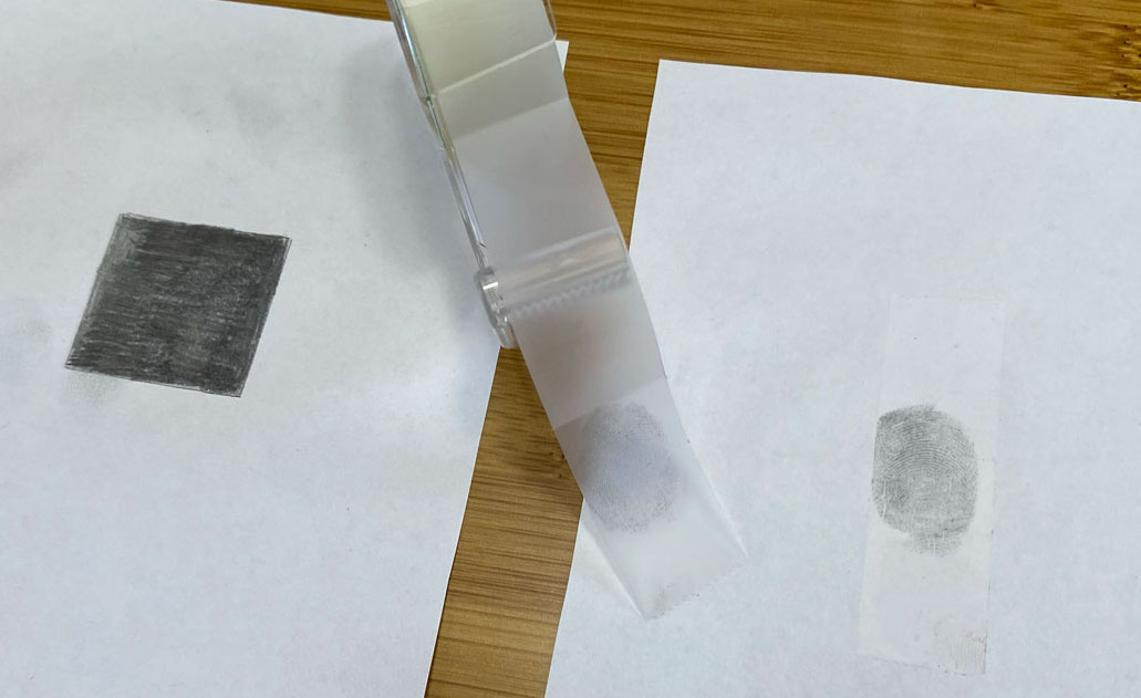
- To make an ink pad variation, rub a pencil on a piece of printer paper, parchment paper or tracing paper several times until an area of about 3 by 3 centimeters (1.2 by 1.2 inches) is completely grey, as shown in Figure 3 (the paper on the left).
- Use a moist towelette to clean the person’s right index finger.
- Thoroughly dry the finger with a paper towel.
- Press and slide each side of the right index fingertip one time over the pad.
- Then roll the grey fingertip onto the sticky side of a piece of clear tape. The result will look like the tape in Figure 3.
- Use another towelette to clean the person’s grey finger.
- Cut off the piece of tape containing the fingerprint and stick it onto a piece of white paper, as shown in Figure 3.
- Perfect your technique until the fingerprints come out clear each time.
- When your prints start to fade, rub your pencil a couple of times over your pad and try again.
2. Make up a consent form for your science project. Because fingerprints can be used to identify people, you will need their consent to take and use their fingerprints. The Science Buddies resource on Projects Involving Human Subjects will give you some additional information on getting consent.
3. Collect fingerprints of pairs of siblings and of pairs of unrelated people.
- Make sure they sign a consent form before you take the fingerprint.
- Use the cleaning and printing system you developed in step 1 to take one fingerprint of each person’s right index finger.
- Label each fingerprint with a unique code, which will tell you which pair the fingerprint belongs to and whether that is a sibling pair or an unrelated pair. An example of an appropriate code would be to assign each pair a number and each individual a letter. Siblings would be labeled as subjects A and B, while unrelated individuals would be labeled as subjects D and Z. Thus, fingerprints from a sibling pair might carry the codes 10A and 10B while fingerprints from an unrelated pair might be labeled 11D and 11Z.
- Collect fingerprints from at least 15 sibling pairs and 15 unrelated pairs. For unrelated pairs, you can actually reuse your sibling data by pairing them up differently. As an example, you could pair sibling 1A with sibling 2B since these individuals are not related to each other. The more pairs you look at in your science project, the stronger your conclusions will be! For a more in-depth look at how the number of participants affects the reliability of your conclusions, see the Science Buddies resource Sample Size: How Many Survey Participants Do I Need?
4. Examine each fingerprint and characterize it as a whorl, arch or loop pattern. You can use a magnifying glass if you have one. In your lab notebook, make a data table like Table 1, creating a separate row for each person, and fill it out.
In your lab notebook, make a data table like this one and fill it out using the fingerprint pattern data you collected. Be sure to make a separate row for each person.
5. To analyze your data, calculate the percentage of related pairs whose fingerprint patterns match and the percentage of unrelated pairs whose fingerprint patterns match. Advanced students can calculate the margin of error. The Science Buddies resource Sample Size: How Many Survey Participants Do I Need? can help you with this.
6. Make a visual representation of your data. A pie chart or bar graph will work well for this data. Advanced students can indicate the margin of error on their graph.
7. Compare the percentage of related pairs whose fingerprint patterns match to the percentage of unrelated pairs whose fingerprint patterns match.
- Are they the same? Is the difference significant taking the margin of error into account? Which one is higher?
- What does this tell you about whether fingerprint patterns are genetic?
- Identical twins share (nearly) 100 percent of their DNA. Does your data include any identical twins? Do they have the same fingerprint pattern?
- How do your results change if you compare all 10 fingers rather than just one? Do all 10 fingers from the same person have the same fingerprint?
- Toes also have ridge patterns. Do “toe prints” follow the same rules as fingerprints?
- Are some patterns more common than others?
- If you make more quantitative measurements of the fingerprint patterns, can they be used to predict sibling pairs? With what degree of accuracy?
- If fingerprints are unique, why do misidentifications occur in forensics? How easy or hard is it to match a fingerprint with an individual?
- Read about statistics and use a mathematical test (like Fisher’s exact test) to determine if your findings are statistically relevant. To do this, you will need to make sure you understand p values and you will need to think about whether your sample size is large enough. Online calculators, like the one from GraphPad Software , are good resources for this analysis.
This activity is brought to you in partnership with Science Buddies . Find the original activity on the Science Buddies website.
More Stories from Science News Explores on Genetics

A new type of immune cell may cause lifelong allergies

Paw-print DNA lets scientists track out-of-sight polar bears

Here’s how kingfishers avoid concussions during high-speed dives

RNA work that led to COVID-19 vaccines wins 2023 Nobel in medicine

Toddler now thrives after prenatal treatment for a genetic disease

Forensic scientists are gaining an edge on crime

For some kids, their rock-star hair comes naturally

Examining Neandertal and Denisovan DNA wins a 2022 Nobel Prize

Why Do We Have Fingerprints?

In 1910, Thomas Jennings fled a murder scene, but he left behind a clue that would seal his fate: a perfect impression of his fingerprints in the drying paint of a railing, outside the house where he'd committed the crime. Jennings' fingerprints were the first ever to be used as evidence in a criminal investigation , and they led to his conviction for murder in 1911.
Since then, fingerprints have continued to feature as crucial evidence in forensic investigations. These unique identity markers are so ideally suited to the task of busting a crime, that it's almost as if that's why they exist.
But of course, this isn't the case. Which brings us to the question: Why do we have fingerprints, and what biological purpose do they serve?
Related: 10 Things You Didn’t Know About You
Fingers and friction
It turns out, scientists have historically disagreed on the answer.
"People have had two ideas about fingerprints: that they help improve grip, and that they help improve touch perception," said Roland Ennos, a biomechanics researcher and visiting professor of biology at the University of Hull in the United Kingdom.
Ennos has spent part of his career investigating the first idea — that fingerprints give us grip. For a long time, this has been the guiding theory, that fingerprints' miniscule troughs and peaks create friction between our hands and the surfaces we touch.
Sign up for the Live Science daily newsletter now
Get the world’s most fascinating discoveries delivered straight to your inbox.
One piece of evidence to support this theory is that fingertips might work like the rubber tires on cars, whose pliable nature allows them to conform to the surface they're traveling across. In tires, this pliability is paired with trough-like treads that decorate their surface — and this enlarges the tire's surface area, therefore increasing friction and traction, too. Ennos wanted to investigate how well this idea would hold up in a laboratory experiment.
"We wanted to see if finger friction goes up with the contact area like it does in tires," Ennos told Live Science. To find out, the researchers dragged a perspex plate across a person's finger pads, varying the force over different attempts and using fingerprint ink to determine how much of the flesh area was touching the glass.
Surprisingly, these experiments revealed that "the actual area of contact was reduced by the fingerprints, because the valleys didn't make contact," Ennos told Live Science. In other words, compared with the smooth skin that covers the rest of the body, "fingerprints should reduce friction, at least on smooth surfaces."
This doesn't completely debunk the idea that fingerprints aid grip, said Ennos. It's thought that fingerprints might help us grip surfaces in wet conditions, for instance — the channels wicking away water much like the treads on car tires do — to stop our hands from slipping across a surface. Yet, this idea is harder to test because it's difficult to perfectly mimic the behaviour of human fingerprints under these conditions, Ennos said.
But there is the other theory, which might hold more water: the role of fingerprints in aiding touch.
Masterful touch
A few years ago, Georges Debrégeas, a physicist-turned-biologist at Sorbonne University in Paris, was pondering the lack of a conclusive theory on why we have fingerprints, when he became curious about the potential role of touch . Our fingers contain four types of mechanoreceptors, or cells that respond to mechanical stimulation like touch. Debrégeas was especially curious about one particular type of mechanoreceptor — Pacinian corpuscles — which occur about 0.08 inches (2 millimeters) below the surface of the skin in fingertips. "I was interested in Pacinian corpuscles because we knew, from previous experiments, that these specific receptors mediate the perception of fine texture," Debrégeas told Live Science.
These mechanoreceptors are particularly sensitive to tiny vibrations of a precise frequency — 200 hertz — and thus help to give our fingertips their extreme sensitivity. Debrégeas wondered whether fingerprints enhanced this sensitivity.
To find out, he and his colleagues designed a biomimetic tactile sensor, a contraption that resembles the structure of a human finger,, with sensors that would detect vibrations similarly to the way that Pacinian corpuscles do. One version of this device was smooth, and another had a ridged pattern on the surface that mimicked a human fingerprint. When moved over a surface, the ridged one yielded a fascinating discovery : the ridges on the sensor amplified the exact frequency of vibrations that Pacinian corpuscles are so sensitive to.
Acting as a proxy for human fingertips, the contraption suggested that our fingerprints would similarly channel these precise vibrations to sensors beneath the skin. . By amplifying this fine and detailed sensory information, the theory is that fingerprints therefore increase our tactile sensitivity severalfold. "The fact that you put fingerprints on the skin completely changes the nature of the signals," Debrégeas said.
But what's the benefit of having such hypersensitive fingertips?
For millennia, our hands have been crucial tools for finding and eating food, and helping us navigate the world. Those tasks are mediated by touch. Sensitivity to textures, in particular, might be evolutionarily beneficial because it has helped us detect the right kind of food: “The reason why we need to detect and separate textures is that we want to separate the good food from the bad food,” Debrégeas explained. A fine sense of touch might help us to avoid rotting or infected items.
Adding weight to the idea, Debregéas noted that the pairing of fingerprints and Pacinian corpuscles also exists in other animals like chimpanzees and koalas, which partially rely on tactile sensitivity to help them find their food.
Debregéas emphasised, however, that his experiment isn't proof that fingerprints evolved for this purpose. But it's a compelling and elegant thesis, nevertheless. "It seems like everything matches," he said.
Loose ends and new questions
Even so, Debrégeas actually thinks that fingerprints might serve the goals of both touch and grip. “The reason we are so good at manipulating and handling things is because we have this exquisite sense of touch - a constant feedback loop between what we touch and what we feel,” he explained. That “allows us to correct in real time the force with which we’re going to grip the object.”
For instance, if something slips while you’re holding it, you need to be able to detect the change in its surface with sensitive fingertips, in order to maintain your grip . So Debrégeas thinks it’s possible that our fine sense of touch and precise grip actually co-evolved
Ennos ponders yet another possible explanation: Fingerprints might prevent blisters, he believes. "A final idea I favor is that the ridges reinforce skin in some directions and help it resist blistering, while still allowing it to stretch at right angles, so the skin maintains contact," he said. "This is a bit like the reinforcements in tires."
To Ennos, these many possibilities intrigue him.
So, where does this leave us? It seems that despite offering irrefutable forensic evidence to detectives and police, for now, our fingerprints remain something of an enigma.
- Do Identical Twins Have Identical Fingerprints?
- Why Do We Hiccup?
- Why Do Smells Trigger Strong Memories?
Originally published on Live Science .

Emma Bryce is a London-based freelance journalist who writes primarily about the environment, conservation and climate change. She has written for The Guardian, Wired Magazine, TED Ed, Anthropocene, China Dialogue, and Yale e360 among others, and has masters degree in science, health, and environmental reporting from New York University. Emma has been awarded reporting grants from the European Journalism Centre, and in 2016 received an International Reporting Project fellowship to attend the COP22 climate conference in Morocco.
Why do people feel like they're being watched, even when no one is there?
Why do babies rub their eyes when they're tired?
Scientists may have pinpointed the true origin of the Hope Diamond and other pristine gemstones
- Patzcakes It doesn't explain why there's no two people with the same fingerprints. Just saying. 😶 Reply
- kennymac825 Then why do racing tires have no treads? Also often when I try to remove an egg from a full carton it's difficult to remove but when I wet my fingers it comes out easy-peasy? Reply
kennymac825 said: Then why do racing tires have no treads? Also often when I try to remove an egg from a full carton it's difficult to remove but when I wet my fingers it comes out easy-peasy?
- HelloWorld Regarding the paragraph for friction I believe that they missed something incredibly important. Assuming equal weight (force), decreased Surface area by the fingerprints relates to increased contact pressure! Increased relative contact pressure would increase the variations in contact pressure between two neighboring points. Perhaps this is written in one of their scientific papers somewhere else but I believe this should be studied. That increased contact pressure at variable increments (over each of the fingerprint ridges) would allow for efficient tactile perception as variable pressure would be easier to detect in finite incremental segments, like pixels. Please reach out to me/credit me/comment below if you’re interested to speak further on the subject. Reply
- View All 4 Comments
Most Popular
- 2 Scientists are one step closer to knowing the mass of ghostly neutrinos — possibly paving the way to new physics
- 3 Giant, 82-foot lizard fish discovered on UK beach could be largest marine reptile ever found
- 4 See the explosive 'devil comet' get its tail ripped off by a solar storm days before its close approach to the sun
- 5 Global 'time signals' subtly shifted as the total solar eclipse reshaped Earth's upper atmosphere, new data shows
- 2 Giant, 82-foot lizard fish discovered on UK beach could be largest marine reptile ever found
- 3 What's the largest waterfall in the world?
- 4 Southern Grasshopper mouse: The tiny super-predator that howls at the moon before it kills
- 5 Rare 'porcelain gallbladder' found in 100-year-old unmarked grave at Mississippi mental asylum cemetery
- Open access
- Published: 28 June 2011
A biochemical hypothesis on the formation of fingerprints using a turing patterns approach
- Diego A Garzón-Alvarado 1 &
- Angelica M Ramírez Martinez 2
Theoretical Biology and Medical Modelling volume 8 , Article number: 24 ( 2011 ) Cite this article
10k Accesses
14 Citations
64 Altmetric
Metrics details
Fingerprints represent a particular characteristic for each individual. Characteristic patterns are also formed on the palms of the hands and soles of the feet. Their origin and development is still unknown but it is believed to have a strong genetic component, although it is not the only thing determining its formation. Each fingerprint is a papillary drawing composed by papillae and rete ridges (crests). This paper proposes a phenomenological model describing fingerprint pattern formation using reaction diffusion equations with Turing space parameters.
Several numerical examples were solved regarding simplified finger geometries to study pattern formation. The finite element method was used for numerical solution, in conjunction with the Newton-Raphson method to approximate nonlinear partial differential equations.
Conclusions
The numerical examples showed that the model could represent the formation of different types of fingerprint characteristics in each individual.
Fingerprints represent a particular characteristic for each individual [ 1 – 10 ]. These enable individuals to be identified through the embossed patterns formed on fingertips. Characteristic patterns are also formed on the palms of the hands and soles of the feet [ 1 ]. Their origin and development is still unknown but it is believed to have a strong genetic component, although it is not the only thing determining its formation. Each fingerprint is a papillary drawing composed by papillae and rete ridges (crests) [ 1 – 6 ]. These crests are epidermal ridges having unique characteristics [ 1 ].
Characteristic fingerprint patterns begin their formation by the sixth month of gestation [ 1 – 6 ]. Such formation is unchangeable until an individual's death. No two fingerprints are identical; they thus become an excellent identification tool [ 1 , 2 ]. Various theories have been proposed concerning fingerprint formation; among the most accepted are those that consider differential forces on the skin (mechanical theory) [ 1 , 6 , 7 ] and those having a genetic component [ 1 , 6 , 10 ]. From a mechanical point of view, it has been considered that fingerprints are produced by the interaction of nonlinear elastic forces between the dermis and epidermis [ 7 ]. This theory considers that the growth of the fingers in the embryo (dermis) is different than growth in the epidermis, resulting in folds in the skin surface [ 7 ]. Figure 1 shows a mechanical explanation for the formation of the folds that give rise to fingerprints.

Fingerprint formation Taken from [ 7 ]. An explanation for the formation of grooves forming a fingerprint. The first figure on the left (top) shows the epidermis and dermis. Right: rapid growth of the basal layer. Below (right) compressive loads are generated. Left: generation of wrinkles due to mechanical loads.
Fingers are separated from each other in the fetus during embryonic formation during the sixth week, generating certain asymmetries in each finger's geometry [ 10 ]. The fingertips begin to be defined from the seventh week onwards [ 1 , 10 ]. The first waves forming the fingerprint begin to take shape from the tenth week; these are patterns which keep growing and deform until the whole fingertip has been completed [ 10 ]. Fingerprint formation finishes at about week 19 [ 10 ]. From this time on, the fingerprints stop changing for the rest of an individual's lifetime. Figure 2 shows the stages of fingerprint formation.

Stages of Fingerprint formation Taken from [ 9 ]. Fingerprint formation. a) primary formation, b) the first loop is generated, c) development. d) complete formation, e) side view, f) wear.
Alternately to the proposal made by Kucken [ 7 ], this paper presents a hypothesis about fingerprint formation from a biochemical effect. The proposed model uses a reaction-diffusion-convection (RDC) system. Following a similar approach to that used in [ 11 , 12 ], a glycolysis reaction model has been used to simulate the appearance of patterns on fingertips. A solution method on three dimensional surfaces using total Lagrangian formulation is provided for resolving the reaction diffusion (RD) equations. Equations whose parameters are in the Turing space have been used for pattern formation; therefore, the patterns found are Turing patterns which are stable in time and unstable in space. Such stability is similar to that found in fingerprint formation. The model explained in [ 11 ] was used for fold growth where the formation of the folds depends on the concentration of a biochemical substance present on the surface of the skin.
Reaction-diffusion (RD) system
Following a biochemical approach, it was assumed that a RD system could control fingerprint pattern formation. For this purpose, an RD system was defined for two species, given by (1):
where u 1 and u 2 were the concentrations of chemical species present in reaction terms f and g, d was the dimensionless diffusion coefficient and γ was a constant in a dimensionless system [ 12 ].
RD systems have been extensively studied to determine their behavior in different scenarios regarding parameters [ 12 , 13 ], geometrics [ 13 , 14 ] and for different biological applications [ 15 – 17 ]. One area that has led to developing extensive work on RD equations has been the formation of patterns which are stable in time and unstable in space [ 18 , 19 ]. In particular, Turing [ 20 ], in his book, "The chemical basis of morphogenesis," developed the necessary conditions for spatial pattern formation. The conditions for pattern formation determined Turing space given by the following restrictions (2):
Equations ( 1 ) and constraints (2) led to developing the dynamic system branch of research [ 11 , 18 ]: Turing instability. Turing pattern theory has helped explain the formation of complex biological patterns such as the spots found on the skin of some animals [ 15 , 16 ] and morphogenesis problems [ 10 ]. It has also been experimentally proven that the behavior of some RD systems produce traveling wave and stable spatial patterns [ 21 – 23 ].
The equations used for predicting pattern formation in this paper were those for glycolysis [ 24 ], given by:
Epidermis strain
The ideas suggested in [ 10 , 25 , 26 ] were used to strain the fingertip surface regarding the substances (morphogens) present in the domain; i.e. surface S , was strained according to its normal N and the amount of molecular concentration (u 2 ) at each material point, therefore:
where K was a constant determining growth rate.
Including the term for surface growth (equation ( 4 )) modifies equation ( 1 ), which presented a new term taking into account the convection and dilation of the domain given by:
The finite element method [ 27 ] was used to solve the RDC system described above in (5) and the Newton-Raphson method [ 28 ] to solve the non-linear system of partial differential equations arising from the formulation. The seed coat surface pattern growth field was imposed by solving equation ( 4 ), giving the new configuration (current) and velocity field to be included in the RD problem.
The solution of the RD equations by using the finite element method is shown below.
Solution for RDC system
Formulating the RD system, including convective transport, could be written as (6) [ 24 ]:
where u 1 and u 2 were the RD system's chemical variables. This equation could also be written in terms of total derivative (7) [ 24 ]:
where it should be noted that
According to the description in [ 29 ], then the RDC system in the initial configuration, or reference Ω 0 (with coordinates in X(x) ), was given by the following equation, written in terms of material coordinates:
Therefore, equation ( 8 ) gave the general weak form for (9) [ 27 ].
where U was either of the two studied species (U 1 or U 2 ), W was the weighting, J was the Jacobian (and equaled the determinant for strained gradient F ) and C -1 was the inverse of the Cauchy-Green tensor on the right [ 27 , 28 ].
In the case of total Lagrangian formulation, the calculation was always done in the initial reference configuration. Therefore, the solution for system (8) and (9) began with the discretization of the variables U 1 and U 2 by (10) [ 27 ]:
where nnod was the number of nodes, U 1 and U 2 were the vectors containing U 1 and U 2 values at nodal points and superscript h indicated the variable discretization in finite elements. The Newton-Raphson method residue vectors were obtained by choosing weighting functions equal to shape functions (Galerkin standard) given by [ 27 ] (11):
where J was strained gradient determinant, C -1 was the inverse of the Cauchy-Green tensor on the right p, s = 1, ..., nnod and I, J = 1, .., dim , where dim was the dimension in which the problem was resolved. Therefore, using equations ( 11 ) and ( 12 ), the Newton-Raphson method could be implemented to solve the RD system using its material description. It should be noted that (11) and (12) were integrated in the initial configuration [ 29 ].
Applying the velocity fields
Equation ( 4 ) was used to calculate the movement of the mesh and the velocity at which the domain was strained, integrated by Euler's method, given by [ 28 ]:
where S t+dt and S t were the surface configuration in state t and t+dt. Therefore, velocity was given by (14):
where the velocity term had direction and magnitude depending on the material point of surface S.
Aspects of computational implementation
The formulation described above was used for implementing the RD model using the finite element method. It should be noted that although the surface was orientated in a 3D space, the numerical calculations were done in 2D. The normal for each element (Z') was thus found and the prime axes (X'Y') forming a parallel plane to the element plane were located. The geometry was enmeshed by using first order triangular elements with three nodes. Therefore, the calculation was simplified from a 3D system to a system which solved two-dimensional RD models at every instant of time. The relationship between the X'Y'Z 'and XYZ axes could be obtained by a transformation matrix T [ 29 ].
A program in FORTRAN was used for solving the system of equations resulting from the finite element method with the Newton-Raphson method and the following examples were solved on a Laptop having 4096 MB of RAM and 800 MHz processor speed. In all cases, the dimensionless problem was solved with random conditions around the steady state [ 12 , 24 ] for the RD system.
The mesh used is shown in Figure 3 . This mesh was made on a 1 cm long, 0.5 cm radius ellipsoid. The number of triangular elements was 5,735 and the number of nodes 2,951. The time step used in the simulation was dt = 2 (dimensionless). The total simulation time was t = 100.

Mesh used in the simulation . Mesh used in developing the problem. In this figure the mesh has 5735 triangular elements and 2951 nodes.
The dimensionless parameters of the RD system of glycolysis were given by d = 0.08, δ = 1.2 and κ = 0.06 for Figure 4a , 4b and 4c ) d = 0.06, δ = 1.2 and κ = 0.06. Therefore the steady state was given at the point of equilibrium ( u 1 ,u 2 ) 0 = (0.8,1.2), so that the initial conditions were random around steady state [ 12 , 14 ]. K = 0.05 in equations ( 4 ) and ( 13 ) was used for all glycolysis simulations.

Results of the simulation of Fingerprint a) photo of the fingerprints, b) results for parameters d = 0 .08, δ = 1.2 and κ = 0.06. c) results for parameters d = 0.06, δ = 1.2 and κ = 0.06.
Figure 4b )- 4c ) shows surface pattern evolution. The formation of labyrinths and blind spots in the grooves approximating the shape of the fingerprint patterns can be observed (Figure 4a ). The pattern obtained was given by bands of high concentration of a chemical species, for which the domain had grown in the normal direction to the surface and hence generated its own fingerprint grooves.
Figure 5 shows temporal evolution during the formation of folds and furrows on the fingertip. In 5a) shows that there was no formation whatsoever of folds. In b), small bumps began to form, in the entire domain, which continued to grow and form the grooves, as shown in Figure 5f ).

Stages of Fingerprint formation simulation . Different instants of time in the evolution of the folds and grooves forming the fingerprint. a) t = 0, b) t = 20, c) t = 40, d) t = 60, e) t = 80 f) t = 100. Time is dimensionless.
Discussion and conclusions
This paper has presented a phenomenological model based on RD equations to predict the formation of rough patterns on the tips of the fingers, known as fingerprints. The application of the RD models with Turing space parameters is an area of constant work and controversy in biology [ 31 , 32 ] and has attracted recent interest due to the work of Sick et al ., [ 32 ] confirming the validity of RD equations in a model of the appearance of the hair follicle. From this point of view, the work developed in this article has illustrated RD equation validity for representing complex biological patterns, such as patterns formed in fingerprints.
This paper proposes the existence of a reactive system (activator-inhibitor) on the skin surface giving an explanation for the patterns found. The high stability of the emergence of the patterns can also be explained, i.e. the repetition of the patterns was due to a specialized biochemical system allowing the formation of wrinkles in the fingerprints and skin pigmentation.
The formulation of a system of RD equations acting under domain strain was programmed to test this hypothesis. Continuum mechanics thus led to the general form of the RD equations in two- and three-dimensions on domains presenting strain. The resulting equations were similar to those shown in [ 33 ], where major simplifications were carried out on field dilatation. The RD system was solved by the finite element method, using a Newton-Raphson approach to solve the nonlinear problem. This allowed longer time steps and obtaining solutions closer to reality. The results showed that RD equations have continuously changing patterns.
Additionally, it should be noted that the results obtained with the RD mathematical model was based on assumptions and simplifications that should be discussed for future models.
The model was based on the assumption of a tightly coupled biochemical system (non-linear) between an activator and an inhibitor generating Turing patterns. As far as the authors know, this assumption has not been tested experimentally, so the model is a hypothesis to be tested in future research. It is also feasible, as in other biological models (see [ 7 ]), that there were a large number of chemical factors (morphogens) involved, interacting to form superficial patterns found in the fingers. In the case of patterns with superficial roughness, the biochemical system could also interact with its own mechanical growth factors. Therefore, determining the exact influence of each biochemical and mechanical factor on the formation of surface patterns becomes an experimental challenge that will reveal the morphogenesis of fingerprints.
Kucken M, Newell A: Fingerprint formation. Journal of theoretical biology. 2005, 235 (1): 71-83. 10.1016/j.jtbi.2004.12.020.
Article PubMed Google Scholar
Kucken M, Newell A: A model for fingerprint formation. EPL (Europhysics Letters). 2004, 68: 141-146. 10.1209/epl/i2004-10161-2.
Article Google Scholar
Bonnevie K: Studies on papillary patterns of human fingers. Journal of Genetics. 1924, 15 (1): 1-111. 10.1007/BF02983100.
Hale A: Breadth of epidermal ridges in the human fetus and its relation to the growth of the hand and foot. The Anatomical Record. 1949, 105 (4): 763-776. 10.1002/ar.1091050409.
Article CAS PubMed Google Scholar
Hale A: Morphogenesis of volar skin in the human fetus. American Journal of Anatomy. 1952, 91 (1): 147-181. 10.1002/aja.1000910105.
Hirsch W: Morphological evidence concerning the problem of skin ridge formation. Journal of Intellectual Disability Research. 1973, 17 (1): 58-72.
Article CAS Google Scholar
Kucken M: Models for fingerprint pattern formation. Forensic science international. 2007, 171 (2-3): 85-96. 10.1016/j.forsciint.2007.02.025.
Jain AK, Prabhakar S, Pankanti S: On the similarity of identical twin fingerprints. Pattern Recognition. 2002, 35 (11): 2653-2663. 10.1016/S0031-3203(01)00218-7.
Bonnevie K: Die ersten Entwicklungsstadien der Papillarmuster der menschlichen Fingerballen. Nyt Mag Naturvidenskaberne. 1927, 65: 19-56.
Google Scholar
Cummins H, Midlo C: Fingerprints, palms and soles: An introduction to dermatoglyphics. 1961, Dover Publications Inc. New York, 778:
Cartwright J: Labyrinthine Turing pattern formation in the cerebral cortex. Journal of theoretical biology. 2002, 217 (1): 97-103. 10.1006/jtbi.2002.3012.
Madzvamuse A: A numerical approach to the study of spatial pattern formation. D Phil Thesis. 2000, United Kingdom: Oxford University
Meinhardt H: Models of biological pattern formation. 1982, Academic Press, New York, 6:
Madzvamuse A: Time-stepping schemes for moving grid finite elements applied to reaction-diffusion systems on fixed and growing domains. Journal of computational physics. 2006, 214 (1): 239-263. 10.1016/j.jcp.2005.09.012.
Madzvamuse A, Sekimura T, Thomas R, Wathen A, Maini P: A moving grid finite element method for the study of spatial pattern formation in Biological problems. Morphogenesis and Pattern Formation in Biological Systems-Experiments and Models, Springer-Verlag, Tokyo. Edited by: T. Sekimura, S. Noji, N. Nueno and P.K. Maini. 2003, 59-65.
Chapter Google Scholar
Madzvamuse A, Wathen AJ, Maini PK: A moving grid finite element method applied to a model biological pattern generator* 1. Journal of computational physics. 2003, 190 (2): 478-500. 10.1016/S0021-9991(03)00294-8.
Madzvamuse A, Thomas RDK, Maini PK, Wathen AJ: A numerical approach to the study of spatial pattern formation in the Ligaments of Arcoid Bivalves. Bulletin of mathematical biology. 2002, 64 (3): 501-530. 10.1006/bulm.2002.0283.
Gierer A, Meinhardt H: A theory of biological pattern formation. Biological Kybernetik. 1972, 12 (1): 30-39. 10.1007/BF00289234.
Chaplain MG, Ganesh AJ, Graham I: Spatio-temporal pattern formation on spherical surfaces: Numerical simulation and application to solid tumor growth. J Math Biol. 2001, 42: 387-423. 10.1007/s002850000067.
Turing A: The chemical basis of morphogenesis. Philosophical Transactions of the Royal Society of London Series B, Biological Sciences. 1952, 237 (641): 37-72. 10.1098/rstb.1952.0012.
De Wit A: Spatial patterns and spatiotemporal dynamics in chemical systems. Adv Chem Phys. 1999, 109: 435-513.
CAS Google Scholar
Maini PK, Painter KJ, Chau HNP: Spatial pattern formation in chemical and biological systems. Journal of the Chemical Society, Faraday Transactions. 1997, 93 (20): 3601-3610. 10.1039/a702602a.
Kapral R, Showalter K: Chemical waves and patterns. 1995, Kluwer Academic Pub, 10:
Book Google Scholar
Garzón D: Simulación de procesos de reacción-difusión: aplicación a la morfogénesis del tejido Óseo. 2007, Universidad de Zaragoza, Ph.D. Thesis
Harrison LG, Wehner S, Holloway D: Complex morphogenesis of surfaces: theory and experiment on coupling of reaction-diffusion patterning to growth. Faraday Discussions. 2002, 120: 277-293.
Holloway D, Harrison L: Pattern selection in plants: coupling chemical dynamics to surface growth in three dimensions. Annals of botany. 2008, 101 (3): 361-
Article PubMed Central PubMed Google Scholar
T.J.R , Hughes : The finite element method: linear static and dynamic finite element analysis. 2003, New York: Courier Dover Publications
Hoffman J: Numerical methods for engineers and scientists. 1992, McGraw-Hil
Holzapfel GA: Nonlinear solid mechanics: a continuum approach for engineering. 2000, John Wiley & Sons, Ltd
Belytschko T, Liu W, Moran B: Nonlinear finite elements for continua and structures. 2000, John Wiley and Sons, 36:
Crampin EJ, Maini PK: Reaction-diffusion models for biological pattern formation. Methods and Applications of Analysis. 2001, 8 (3): 415-428.
Sick S, Reinker S, Timmer J, Schlake T: WNT and DKK determine hair follicle spacing through a reaction-diffusion mechanism. Science. 2006, 314 (5804): 1447-1450. 10.1126/science.1130088.
Madzvamuse A, Maini PK: Velocity-induced numerical solutions of reaction-diffusion systems on continuously growing domains. Journal of computational physics. 2007, 225 (1): 100-119. 10.1016/j.jcp.2006.11.022.
Download references
Acknowledgements
This work was financially supported by Division de Investigación de Bogotá, of Universidad Nacional de Colombia, under title Modelling in Mechanical and Biomedical Engineering, Phase II.
Author information
Authors and affiliations.
Associate Professor, Mechanical and Mechatronics Engineering Department,, Universidad Nacional de Colombia, Engineering Modeling and Numerical Methods Group (GNUM),, Bogotá,, Colombia
Diego A Garzón-Alvarado
Professor, Mechanical Engineering Department,, Fundación Universidad Central,, Bogotá,, Colombia
Angelica M Ramírez Martinez
You can also search for this author in PubMed Google Scholar
Corresponding author
Correspondence to Diego A Garzón-Alvarado .
Additional information
Competing interests.
The authors declare that they have no competing interests.
Authors' contributions
The work was made by equal parts, in manuscript, modelling and numerical simulation. All authors read and approved the final manuscript.
Authors’ original submitted files for images
Below are the links to the authors’ original submitted files for images.
Authors’ original file for figure 1
Authors’ original file for figure 2, authors’ original file for figure 3, authors’ original file for figure 4, authors’ original file for figure 5, rights and permissions.
This article is published under license to BioMed Central Ltd. This is an Open Access article distributed under the terms of the Creative Commons Attribution License ( http://creativecommons.org/licenses/by/2.0 ), which permits unrestricted use, distribution, and reproduction in any medium, provided the original work is properly cited.
Reprints and permissions
About this article
Cite this article.
Garzón-Alvarado, D.A., Ramírez Martinez, A.M. A biochemical hypothesis on the formation of fingerprints using a turing patterns approach. Theor Biol Med Model 8 , 24 (2011). https://doi.org/10.1186/1742-4682-8-24
Download citation
Received : 26 May 2011
Accepted : 28 June 2011
Published : 28 June 2011
DOI : https://doi.org/10.1186/1742-4682-8-24
Share this article
Anyone you share the following link with will be able to read this content:
Sorry, a shareable link is not currently available for this article.
Provided by the Springer Nature SharedIt content-sharing initiative
- Fingerprint
- Turing pattern
- numerical solution
- finite element
- continuum mechanics
Theoretical Biology and Medical Modelling
ISSN: 1742-4682
- Submission enquiries: Access here and click Contact Us
- General enquiries: [email protected]
Why Do We Have Fingerprints?
- Cell Biology
- Weather & Climate
- B.A., Biology, Emory University
- A.S., Nursing, Chattahoochee Technical College
For over 100 years scientists have believed that the purpose of our fingerprints is to improve our ability to grip objects. But researchers discovered that fingerprints do not improve grip by increasing friction between the skin on our fingers and an object. In fact, fingerprints actually reduce friction and our ability to grasp smooth objects.
While testing the hypothesis of fingerprint friction, University of Manchester researchers discovered that skin behaves more like rubber than a normal solid. In fact, our fingerprints reduce our ability to grasp objects because they reduce our skin's contact area with the objects we hold. So the question remains, why do we have fingerprints? No one knows for sure. Several theories have arisen suggesting that fingerprints may help us to grasp rough or wet surfaces, protect our fingers from damage, and increase touch sensitivity.
Key Takeaways: Why Do We Have Fingerprints?
- Fingerprints are ridged patterns that form on our fingertips. Several theories have arisen as to why we have fingerprints but no one knows for sure.
- Some scientists believe that fingerprints may provide protection for our fingers or increase our sensitivity to touch. Studies have shown that fingerprints actually inhibit our ability to grasp objects.
- Fingerprints consist of arch, loop, and whorl patterns that form in the seventh month of fetal development. No two people have identical fingerprints, not even twins.
- Those with the rare genetic condition known as adermatoglyphia are born without fingerprints.
- The unique bacteria that live on our hands can be used as a type of fingerprint.
How Fingerprints Develop
D. Sharon Pruitt Pink Sherbet Photography / Getty Images
Fingerprints are ridged patterns that form on our fingertips. They develop while we are in our mother's womb and are formed completely by the seventh month. We all have unique, individual fingerprints for life. Several factors influence fingerprint formation. Our genes influence the patterns of ridges on our fingers, palms, toes, and feet. These patterns are unique even among identical twins. While twins have identical DNA , they still have unique fingerprints. This is because a host of other factors, in addition to genetic makeup, influence fingerprint formation. The location of the fetus in the womb, the flow of amniotic fluid, and the length of the umbilical cord are all factors that play a role in shaping individual fingerprints.
Fingerprints consist of patterns of arches , loops , and whorls . These patterns are formed in the innermost layer of the epidermis known as the basal cell layer. The basal cell layer is located between the outermost layer of skin (epidermis) and the thick layer of skin that lies beneath and supports the epidermis known as the dermis. Basal cells constantly divide to produce new skin cells, which are pushed upward to the layers above. The new cells replace older cells that die and are shed. The basal cell layer in a fetus grows faster than the outer epidermis and dermis layers. This growth causes the basal cell layer to fold, forming a variety of patterns. Because fingerprint patterns are formed in the basal layer, damage to the surface layer will not alter fingerprints.
Why Some People Don't Have Fingerprints
Dermatoglyphia , from the Greek derma for skin and glyph for carving, are the ridges that appear on the fingertips, palms, toes, and soles of our feet. The absence of fingerprints is caused by a rare genetic condition known as adermatoglyphia. Researchers have discovered a mutation in the gene SMARCAD1 that may be the cause for the development of this condition. The discovery was made while studying a Swiss family with members that exhibited adermatoglyphia.
According to Dr. Eli Sprecher from Tel Aviv Sourasky Medical Center in Israel, "We know that fingerprints are fully formed by 24 weeks after fertilization and do not undergo any modification throughout life. However, the factors underlying the formation and pattern of fingerprints during embryonic development are largely unknown." This study has shed some light on fingerprint development as it points to a specific gene that is involved in the regulation of fingerprint development. Evidence from the study also suggests that this particular gene may also be involved in the development of sweat glands.
Fingerprints and Bacteria
Researchers from the University of Colorado at Boulder have shown that bacteria found on the skin can be used as personal identifiers. This is possible because bacteria that live on your skin and reside on your hands are unique, even among identical twins. These bacteria are left behind on the items we touch. By genetically sequencing bacterial DNA, specific bacteria found on surfaces can be matched to the hands of the person from which they came. These bacteria can be used as a type of fingerprint because of their uniqueness and their ability to remain unchanged for several weeks. Bacterial analysis could be a useful tool in forensic identification when human DNA or clear fingerprints can not be obtained.
- Britt, Robert. "Lasting Impression: How Fingerprints Are Created." LiveScience , Purch, http://www.livescience.com/30-lasting-impression-fingerprints-created.html.
- "New Hand Bacteria Study Holds Promise for Forensics Identification." ScienceDaily , ScienceDaily, 16 Mar. 2010, http://www.sciencedaily.com/releases/2010/03/100315161718.htm.
- Nousbeck, Janna, et al. "A Mutation in a Skin-Specific Isoform of SMARCAD1 Causes Autosomal-Dominant Adermatoglyphia." The American Journal of Human Genetics , vol. 89, no. 2, 2011, pp. 302307., doi:10.1016/j.ajhg.2011.07.004.
- "Urban Myth Disproved: Fingerprints Do Not Improve Grip Friction." ScienceDaily , ScienceDaily, 15 June 2009, http://www.sciencedaily.com/releases/2009/06/090612092729.htm.
- Frequently Asked Biology Questions and Answers
- Why Do Fingers Prune in Water?
- The Structure of the Integumentary System
- Epithelial Tissue: Function and Cell Types
- Understanding the Healing Uses of Artificial Skin
- Why Do We Yawn? Physical and Psychological Reasons
- Biology Prefixes and Suffixes: Derm- or -Dermis
- Common Animal Questions and Answers
- Why Are We Ticklish?
- Types of Cells in the Human Body
- Why Do Heat Index and Wind Chill Temperatures Exist?
- What Are Forensic Linguistics?
- Why Do We Use Euphemisms?
- Placoid Scales on Sharks and Rays
- DNA Fingerprinting and Its Uses
- Methicillin-resistant Staphylococcus aureus (MRSA)
The Myth of Fingerprints
Police today increasingly embrace DNA tests as the ultimate crime-fighting tool. They once felt the same way about fingerprinting
Clive Thompson
:focal(331x262:332x263)/https://tf-cmsv2-smithsonianmag-media.s3.amazonaws.com/filer/e0/e6/e0e6fd99-031b-4a3e-b016-22637c12ac5a/extended_fingerprints_art-updated.jpg "hypothesis about fingerprints")
At 9:00 a.m. last December 14, a man in Orange County, California, discovered he’d been robbed. Someone had swiped his Volkswagen Golf, his MacBook Air and some headphones. The police arrived and did something that is increasingly a part of everyday crime fighting: They swabbed the crime scene for DNA.
Normally, you might think of DNA as the province solely of high-profile crimes—like murder investigations, where a single hair or drop of blood cracks a devilish case. Nope: These days, even local cops are wielding it to solve ho-hum burglaries. The police sent the swabs to the county crime lab and ran them through a beige, photocopier-size “rapid DNA” machine, a relatively inexpensive piece of equipment affordable even by smaller police forces. Within minutes, it produced a match to a local man who’d been previously convicted of identity theft and burglary. They had their suspect.
DNA identification has gone mainstream—from the elite labs of “CSI” to your living room. When it first appeared over 30 years ago, it was an arcane technique. Now it’s woven into the fabric of everyday life: California sheriffs used it to identify the victims of their recent wildfires, and genetic testing firms offer to identify your roots if you mail them a sample.

Yet the DNA revolution has unsettling implications for privacy. After all, you can leave DNA on everything you touch—which means, sure, crimes can be more easily busted, but the government can also more easily track you. And while it’s fun to learn about your genealogy, your cheek samples can wind up in places you’d never imagine. FamilyTreeDNA, a personal genetic service, in January admitted it was sharing DNA data with federal investigators to help them solve crimes. Meanwhile consumer DNA testing firm 23andMe announced that it was now sharing samples sent to them with the pharmaceutical giant GlaxoSmithKline to make “novel treatments and cures.”
What happens to a society when there’s suddenly a new way to identify people—to track them as they move around the world? That’s a question that the denizens of the Victorian turn of the century pondered, as they learned of a new technology to hunt criminals: fingerprinting.
For centuries, scholars had remarked on the curious loops and “whorls” that decorated their fingertips. In 1788, the scientist J.C.A. Mayers declared that patterns seemed unique—that “the arrangement of skin ridges is never duplicated in two persons.”
It was an interesting observation, but one that lay dormant until 19th-century society began to grapple with an emerging problem: How do you prove people are who they say they are?
Carrying government-issued identification was not yet routine, as Colin Beavan, author of Fingerprints , writes. Cities like London were booming, becoming crammed full of strangers—and packed full of crime. The sheer sprawl of the population hindered the ability of police to do their work because unless they recognized criminals by sight, they had few reliable ways of verifying identities. A first-time offender would get a light punishment; a habitual criminal would get a much stiffer jail sentence. But how could the police verify whether a perpetrator they hauled in had ever been caught previously? When recidivists got apprehended, they’d just give out a fake name and claim it was their first crime.
“A lot of that is the function of the increasing anonymity of modern life,” notes Charles Rzepka, a Boston University professor who studies crime fiction. “There’s this problem of what Edgar Allan Poe called ‘The Man of the Crowd.’” It even allowed for devious cons. One man in Europe claimed to be “Roger Tichborne,” a long-lost heir to a family baronetcy, and police had no way to prove he was or wasn’t.
Faced with this problem, police tried various strategies for identification. Photographic mug shots helped, but they were painstakingly slow to search through. In the 1880s, a French police official named Alphonse Bertillon created a system for recording 11 body measurements of a suspect, but it was difficult to do so accurately.
The idea of fingerprints gradually dawned on several different thinkers. One was Henry Faulds, a Scottish physician who was working as a missionary in Japan in the 1870s. One day while sifting through shards of 2,000-year-old pottery, he noticed that the ridge patterns of the potter’s ancient fingerprints were still visible. He began inking prints of his colleagues at the hospital—and noticing they seemed unique. Faulds even used prints to solve a small crime. An employee was stealing alcohol from the hospital and drinking it in a beaker. Faulds located a print left on the glass, matched it to a print he’d taken from a colleague, and—presto—identified the culprit.
How reliable were prints, though? Could a person’s fingerprints change? To find out, Faulds and some students scraped off their fingertip ridges, and discovered they grew back in precisely the same pattern. When he examined children’s development over two years, Faulds found their prints stayed the same. By 1880 he was convinced, and wrote a letter to the journal Nature arguing that prints could be a way for police to deduce identity.
“When bloody finger-marks or impressions on clay, glass, etc., exist,” Faulds wrote, “they may lead to the scientific identification of criminals.”
Other thinkers were endorsing and exploring the idea—and began trying to create a way to categorize prints. Sure, fingerprints were great in theory, but they were truly useful only if you could quickly match them to a suspect.
The breakthrough in matching prints came from Bengal, India. Azizul Haque, the head of identification for the local police department, developed an elegant system that categorized prints into subgroups based on their pattern types such as loops and whorls. It worked so well that a police officer could find a match in only five minutes—much faster than the hour it would take to identify someone using the Bertillon body-measuring system. Soon, Haque and his superior Edward Henry were using prints to identify repeat criminals in Bengal “hand over fist,” as Beavan writes. When Henry demonstrated the system to the British government, officials were so impressed they made him assistant commissioner of Scotland Yard in 1901.
Fingerprinting was now a core tool in crime-busting. Mere months after Henry set up shop, London officers used it to fingerprint a man they’d arrested for pickpocketing. The suspect claimed it was his first offense. But when the police checked his prints, they discovered he was Benjamin Brown, a career criminal from Birmingham, who’d been convicted ten times and printed while in custody. When they confronted him with their analysis, he admitted his true identity. “Bless the finger-prints,” Brown said, as Beavan writes. “I knew they’d do me in!”
Within a few years, prints spread around the world. Fingerprinting promised to inject hard-nosed objectivity into the fuzzy world of policing. Prosecutors historically relied on witness testimony to place a criminal in a location. And testimony is subjective; the jury might not find the witness credible. But fingerprints were an inviolable, immutable truth, as prosecutors and professional “fingerprint examiners” began to proclaim.
“The fingerprint expert has only facts to consider; he reports simply what he finds. The lines of identification are either there or they are absent,” as one print examiner argued in 1919.
This sort of talk appealed to the spirit of the age—one where government authorities were keen to pitch themselves as rigorous and science-based.
“It’s this turn toward thinking that we have to collect detailed data from the natural world—that these tiniest details could be more telling than the big picture,” says Jennifer Mnookin, dean of the UCLA law school and an expert in evidence law. Early 20th-century authorities increasingly believed they could solve complex social problems with pure reason and precision. “It was tied in with these ideas of science and progressivism in government, and having archives and state systems of tracking people,” says Simon Cole, a professor of criminology, law, and society at the University of California, Irvine, and the author of Suspect Identities , a history of fingerprinting.
Prosecutors wrung high drama out of this curious new technique. When Thomas Jennings in 1910 was the first U.S. defendant to face a murder trial that relied on fingerprinted evidence, prosecutors handed out blown-up copies of the prints to the jury. In other trials, they would stage live courtroom demonstrations of print-lifting and print-matching. It was, in essence, the birth of the showily forensic policing that we now see so often on “CSI”-style TV shows: perps brought low by implacably scientific scrutiny. Indeed, criminals themselves were so intimidated by the prospect of being fingerprinted that, in 1907, a suspect arrested by Scotland Yard desperately tried to slice off his own prints while in the paddy wagon.
Yet it also became clear, over time, that fingerprinting wasn’t as rock solid as boosters would suggest. Police experts would often proclaim in court that “no two people have identical prints”—even though this had never been proven, or even carefully studied. (It’s still not proven.)
Although that idea was plausible, “people just asserted it,” Mnookin notes; they were eager to claim the infallibility of science. Yet quite apart from these scientific claims, police fingerprinting was also simply prone to error and sloppy work.
The real problem, Cole notes, is that fingerprinting experts have never agreed on “a way of measuring the rarity of an arrangement of friction ridge features in the human population.” How many points of similarity should two prints have before the expert analyst declares they’re the same? Eight? Ten? Twenty? Depending on what city you were tried in, the standards could vary dramatically. And to make matters more complex, when police lift prints from a crime scene, they are often incomplete and unclear, giving authorities scant material to make a match.
So even as fingerprints were viewed as unmistakable, plenty of people were mistakenly sent to jail. Simon Cole notes that at least 23 people in the United States have been wrongly connected to crime-scene prints.* In North Carolina in 1985, Bruce Basden was arrested for murder and spent 13 months in jail before the print analyst realized he’d made a blunder.
Nonetheless, the reliability of fingerprinting today is rarely questioned in modern courts. One exception was J. Spencer Letts, a federal judge in California who in 1991 became suspicious of fingerprint analysts who’d testified in a bank robbery trial. Letts was astounded to hear that the standard for declaring that two prints matched varied widely from county to county. Letts threw out the fingerprint evidence from that trial.
“I don’t think I’m ever going to use fingerprint testimony again,” he said in court, sounding astonished, as Cole writes. “I’ve had my faith shaken.” But for other judges, the faith still holds.
The world of DNA identification, in comparison, has received a slightly higher level of skepticism. When it was first discovered in 1984, it seemed like a blast of sci-fi precision. Alec Jeffreys, a researcher at the University of Leicester in England, had developed a way to analyze pieces of DNA and produce an image that, Jeffreys said, had a high likelihood of being unique. In a splashy demonstration of his concept, he found that the semen on two murder victims wasn’t from the suspect police had in custody.
DNA quickly gained a reputation for helping free the wrongly accused: Indeed, the nonprofit Innocence Project has used it to free over 360 prisoners by casting doubt on their convictions. By 2005, Science magazine said DNA analysis was the “gold standard” for forensic evidence.
Yet DNA identification, like fingerprinting, can be prone to error when used sloppily in the field. One problem, notes Erin Murphy, professor of criminal law at New York University School of Law, is “mixtures”: If police scoop up genetic material from a crime scene, they’re almost certain to collect not just the DNA of the offender, but stray bits from other people. Sorting relevant from random is a particular challenge for the simple DNA identification tools increasingly wielded by local police. The rapid-typing machines weren’t really designed to cope with the complexity of samples collected in the field, Murphy says—even though that’s precisely how some police are using them.
“There’s going to be one of these in every precinct and maybe in every squad car,” Murphy says, with concern. When investigating a crime scene, local police may not have the training to avoid contaminating their samples. Yet they’re also building up massive databases of local citizens: Some police forces now routinely request a DNA sample from everyone they stop, so they can rule them in or out of future crime investigations.
The courts have already recognized the dangers of badly managed DNA identification. In 1989—only five years after Jeffreys invented the technique—U.S. lawyers successfully contested DNA identification in court, arguing that the lab processing the evidence had irreparably contaminated it. Even the prosecution agreed it had been done poorly. Interestingly, as Mnookin notes, DNA evidence received pushback “much more quickly than fingerprints ever did.”
It even seems the public has grasped the dangers of its being abused and misused. Last November, a jury in Queens, New York, deadlocked in a murder trial—after several of them reportedly began to suspect the accused’s DNA had found its way onto the victim’s body through police contamination. “There is a sophistication now among a lot of jurors that we haven’t seen before,” Lauren-Brooke Eisen, a senior fellow at the Brennan Center for Justice, told the New York Times .
To keep DNA from being abused, we’ll have to behave like good detectives—asking the hard questions, and demanding evidence.
*Editor's Note, April 26, 2019: An earlier version of this story incorrectly noted that at least 23 people in the United States had been imprisoned after being wrongly connected to crime-scene prints. In fact, not all 23 were convicted or imprisoned. This story has been edited to correct that fact. Smithsonian regrets the error.
Body of Evidence
Now science can identify you by your ears, your walk and even your scent Research by Sonya Maynard

Get the latest Science stories in your inbox.
/https://tf-cmsv2-smithsonianmag-media.s3.amazonaws.com/accounts/headshot/Clive_Thompson_photo_credit_is_Tom_Igoe.jpg "hypothesis about fingerprints")
Clive Thompson | | READ MORE
Clive Thompson is author of Smarter Than You Think: How Technology is Changing Our Minds for the Better and Coders: The Making of a New Tribe and the Remaking of the World . He is a contributing writer to the New York Times Magazine and Wired . Photo: Tom Igoe.
- COP Climate Change
- Coronavirus (COVID-19)
- Cancer Research
- Diseases & Conditions
- Mental Health
- Women’s Health
- Circular Economy
- Sustainable Development
- Agriculture
- Research & Innovation
- Digital Transformation
- Publications
- Academic Articles
- Health & Social Care
- Environment
- HR & Training
- Health Research
- North America Analysis
- Asia Analysis
- Our Audience
- Marketing Information Pack
- Prestige Contributors
- Testimonials
- North America
The function of fingerprints: How can we grip?

Professor Gun-Sik Park, in the Department of Physics and Astronomy at Seoul National University explores the function of fingerprints from a lens of understanding the mechanism of our human ability to grip
The regulation of moisture levels in fingerprints has been found to play a crucial role in optimizing grip and maximizing friction. Our study revealed that the function of fingerprints is to control the hydration of the fingertips, allowing for precision gripping.
To understand the hydrodynamics of the fingerprint, we used electromagnetic waves in various frequency ranges, including megahertz, terahertz, infrared, and visible light. Our results showed that the fingerprint structure acts as a capillary channel for evaporation, leading to a steady-state hydration condition in either dry or wet conditions.
This research sheds light on the little-understood mechanism of grip in humans, primates, and koalas. Our findings suggest that the fingerprints function as a capillary evaporating channel, contributing to precision grip.
The function of fingerprints
The function of fingerprints has been a topic of interest for some time, with the long-standing belief being that fingerprints help increase friction for better grip. However, recent research has challenged this notion and has instead shown that the ridges of fingerprints actually reduce friction by reducing the contact area. The only established function of fingerprints has been found to be their modulation of friction when rubbed against a finely abraded surface, which enhances tactile sensitivity.
This discovery has led to the development of various tactile stimulating devices, including artificial fingers, used as friction sensors. Further studies have aimed to uncover the relationship between fingerprints, tactile perception, and gripping. It has been suggested that fingerprints greatly change the contact area and friction coefficient as grip force increases, potentially aiding in precision manipulation and gripping tasks.
Despite the advances in our understanding of the relationship between fingerprints and grip, there has been no conclusive evidence that fingerprints assist in gripping. There is still a hypothesis about the role of fingerprints in draining moisture to aid in grip in humid environments. Excessive moisture on the skin can act as a lubricant, reducing friction and causing slipping, however, the hydration level of fully occluded fingerprint skin does not exceed a certain value while gripping. It has been observed that the moisture control of the fingertips tends towards a value that maximizes friction during gripping.
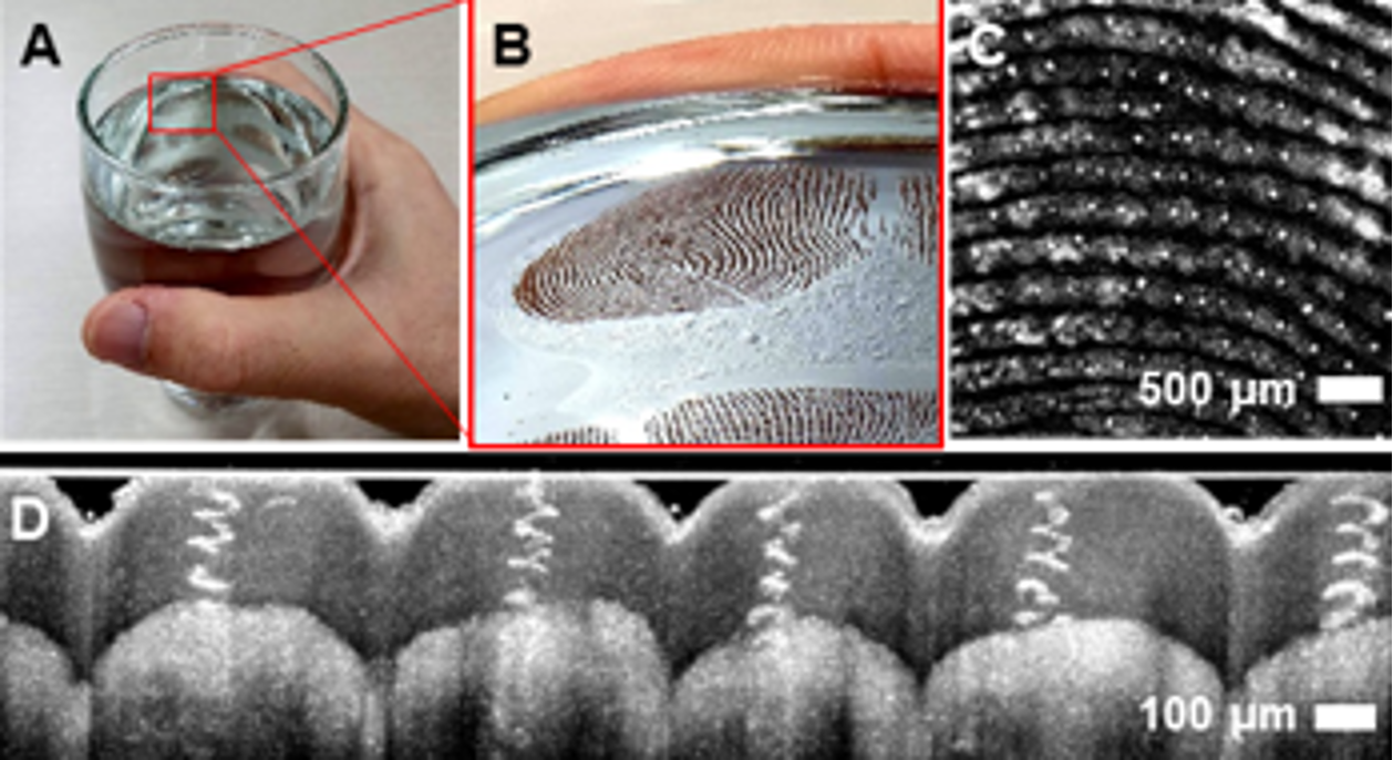
The fingerprint acts as a capillary tube
Several studies have been published that focus on the friction and lubrication of human skin, with results indicating that there is still an unknown mechanism for regulating moisture to optimize the gripping of ridged skin.
In this study, we discovered that the fingerprint acts as a capillary tube where moisture evaporates at the meniscus between the object being held and the fingerprint. This helps maintain a steady-state moisture level, maximizing friction and providing optimal grip. We observed the dynamics of moisture over occlusion time using electromagnetic waves in various regimes, including terahertz and infrared waves and visible light. Our results showed that the hydration level reaches a steady state after around 180 seconds, regardless of whether the fingerprint is “wet” or “dry.” The steady-state hydration levels, friction forces, and occlusion times are dependent on the individual fingerprint’s structures and properties, as well as environmental factors like humidity. Our study also confirmed the tendency for hydration to increase exponentially in “dry” fingerprints and decrease linearly in “wet” fingerprints, as seen through IR waves with optical coherence tomography (OCT).
A microfluidic system at our fingertips
We found that only ridged skin, such as the skin on a fingerprint, can attain a steady-state hydration in the fully occluded state, not flat skin like that on the chest, forearm, or thigh. By using a charged-coupled device (CCD) camera and OCT, we directly visualized the movement of moisture in individual fingerprints over time and observed that evaporation leads to the shedding of excess water through the fingerprint and accumulation of water in the fingerprint valley. This “wet” system of fingerprint-moisture-glass can be considered a microfluidic system, where water films can be trapped by capillarity along the two sharp corners of the interface between the fingerprint and glass.
In conclusion, the function of fingerprints as a capillary channel naturally regulates moisture to maintain optimal friction for gripping. This insight could be useful in the design of tactile sensing devices and optimized haptic interfaces, particularly in developing artificial fingers for human-like touching and gripping.
- PNAS|December 15, 2020|vol.117|no. 50|31665–31673
Seoung-Mok Yum, In-Keun Baek, Dongpyo Hong, Juhan Kim, Kyunghoon Jung, Seontae Kim,Kihoon Eom, Jeongmin Jang, Seonmyeong Kim, Matlabjon Sattorov, Min- Geol Lee, Sungwan Kim,Michael J. Adams, and Gun-Sik Park

Contributor Profile

Gun-Sik Park
Leave a reply cancel reply.
Save my name, email, and website in this browser for the next time I comment.
This article first appeared in Open Access Government April 2023 .
To view the article click here .
License: CC BY 4.0
This work is licensed under Creative Commons Attribution 4.0 International .
What does this mean?
Share - Copy and redistribute the material in any medium or format for any purpose, even commercially.
Adapt - Remix, transform, and build upon the material for any purpose, even commercially.
The licensor cannot revoke these freedoms as long as you follow the license terms.
- Terms & Conditions
- Privacy Policy
- GDPR Privacy Policy
- Marketing Info Pack
- Fee Schedule
- Science Projects
- Project Guides
- STEM Activities
- Lesson Plans
- Video Lessons
- Board index Active Forums (Make all new posts here) Grades 6-8 Grades 6-8: Life, Earth, and Social Sciences
fingerprint hypothesis?
Moderators: AmyCowen , kgudger , bfinio , MadelineB , Moderators
Post by cuppe5 » Mon Nov 28, 2016 7:08 pm
Re: fingerprint hypothesis?
Post by PharmaMan » Mon Nov 28, 2016 10:27 pm
Return to “Grades 6-8: Life, Earth, and Social Sciences”
- Announcements
- Active Forums (Make all new posts here)
- ↳ Grades K-5
- ↳ Grades K-5: Life, Earth, and Social Sciences
- ↳ Grades K-5: Physical Science
- ↳ Grades K-5: Math and Computer Science
- ↳ Grades 6-8
- ↳ Grades 6-8: Life, Earth, and Social Sciences
- ↳ Grades 6-8: Physical Science
- ↳ Grades 6-8: Math and Computer Science
- ↳ Grades 9-12
- ↳ Grades 9-12: Life, Earth, and Social Sciences
- ↳ Grades 9-12: Physical Science
- ↳ Grades 9-12: Math and Computer Science
- ↳ Advanced Science Competitions (Intel ISEF, Intel STS, Siemens Competition, JSHS, etc.)
- ↳ Getting Started
- ↳ Preparing for the Competition
- ↳ STEM Activities
- ↳ Interview Requests
- ↳ Careers in Science
- ↳ Junior Solar Sprint
- ↳ SimPandemic
- ↳ Using SimPandemic
- ↳ General Discussion
- ↳ Preparing for the Science Fair
- ↳ Intel ISEF Preparation
- ↳ Grades K-5: Getting Ready for the Science Fair
- ↳ Grades 6-8: Getting Ready for the Science Fair
- ↳ Grades 9-12: Getting Ready for the Science Fair
- ↳ Physical Science
- ↳ Life, Earth, and Social Sciences
- ↳ Math & Computer Science Sponsored by Hyperion Solutions Corp
- ↳ General Questions
- ↳ Grades 6-8: Wind Tunnel
- ↳ Grades 9-12: Wind Tunnel
- ↳ A Magnetic Primer Designer
- ↳ Bridge Design
- ↳ Build a Gauss Rifle!
- ↳ Build a Simple Circuit
- ↳ Build Your Own Crystal Radio
- ↳ Chemistry of Ice-Cream Making
- ↳ Do Oranges Lose or Gain Vitamin C After Being Picked?
- ↳ Electrolyte Challenge: Orange Juice vs. Sports Drink
- ↳ Enzyme-Catalyzed Reactions
- ↳ Forensic Science: Building Your Own Tool for Identifying DNA
- ↳ From Dull to Dazzling: Using Pennies to Test How pH Affects Copper Corrosion
- ↳ How Do Roots Grow...
- ↳ How Does Soil Affect the pH of Water
- ↳ Investigating the 'Mpemba Effect': Can Hot Water Freeze Faster than Cold Water?
- ↳ Is this connected to that? Use a homemade electronic tester to find out if electricity can flow between two objects.
- ↳ How Are Antibodies Used for Blood Typing?
- ↳ It's All in the Wrist
- ↳ Measuring the Sugar Content on a Liquid with a Laser Pointer
- ↳ Potions and Lotions
- ↳ Shaking Up Some Energy
- ↳ Spin Right 'Round with this Simple Electric Motor
- ↳ Sweet as Sugar
- ↳ The Strength of an Electromagnet
- ↳ Veggie Power! Making Batteries from Fruits and Vegetables
- ↳ Which Orange Juice Has the Most Vitamin C?
- Board index
- All times are UTC
- Free Resources
- Project Search
- Featured Projects
- Member Benefits
1059 Main Avenue, Clifton, NJ 07011
The most valuable resources for teachers and students
(973) 777 - 3113
1059 Main Avenue
Clifton, NJ 07011
07:30 - 19:00
Monday to Friday
123 456 789
Goldsmith Hall
New York, NY 90210
- Why We’re Unique
Fingerprinting
Introduction: (initial observation).
Look at the palm of your hands and fingertips. you will see patterns of ridges that are called fingerprints. The natural body oils and sweat collects in these ridges of skin so that when you touch things, you leave behind an impression of your print. Fingerprint ridges are useful because they give your hands a better grip when you pick something up. But since fingerprints are unique, they have also become a common and foolproof method of identification. They can be used to help solve crimes by identifying criminals. The two basic ideas scientists believe about fingerprints are:
- Fingerprints never change. Small ridges form on a person’s hands and feet before they are born and do not change for as long as the person lives.
- No two fingerprints are alike. The ridges on the hands and feet of all persons have three characteristics (ridge endings, bifurcations and dots) which appear in combinations that are never repeated on the hands or feet of any two persons. A ridge ending is simply the end of a ridge. A bifurcation is a Y-shaped split of one ridge into two. A dot is a very short ridge that looks like a “dot”.

Problem Statement: (Sample)
After each crime, detectives need to find and collect any thing that may possibly lead them to the person or persons who took part in the action. Finger prints are among the most important evidence that can be used to relate a person to a crime. The problem is that finger prints are not visible and we need to use special methods to revel and collect them. This project is an attempt on revealing and identifying finger prints.
This project guide contains information that you need in order to start your project. If you have any questions or need more support about this project, click on the “ Ask Question ” button on the top of this page to send me a message.
If you are new in doing science project, click on “ How to Start ” in the main page. There you will find helpful links that describe different types of science projects, scientific method, variables, hypothesis, graph, abstract and all other general basics that you need to know.
Project advisor
Information Gathering:

More information:
The basic fundamentals in the science of fingerprint identification are permanence and individuality.
Permanence : Fingerprint ridges are formed during the third to fourth month of fetal development. These ridges consist of individual characteristics called ridge endings, bifurcations, dots and many ridge shape variances. The unit relationship of individual characteristics does not naturally change throughout life… until decomposition after death. After formation, an infant’s growing fingerprint ridges are much like drawing a face on a balloon with a ball-point pen and then inflating it to see the same face expand uniformly in all directions. Unnatural changes to fingerprint ridges include deep cuts or injuries penetrating all layers of the epidermis and some diseases such as leprosy.
Permanent scars, disease damage, and temporary changes such as paper cuts appear as jagged edges and sometimes “puckered” ridge detail in opposition to smooth flowing natural formations. Warts can come and go, but generally push apart an area of friction ridges and can disappear completely when the wart is gone because they are not a part of the friction ridge structure. Look at a wart with a magnifying glass and you will notice that the friction ridges “surround” the wart. Senile atrophy of friction skin due to old age causes the ridges to often almost flatten, causing fingerprints with many creases (creases are also unique but not always permanent) and poorly defined ridges. Oddly, newborn infants also often have more creases than clearly defined ridge detail in their barefoot prints. The creases are unique, but change relatively rapidly and often disappear as the infant grows. The best chance of seeing friction skin ridges on newborn infant footprints is to look carefully with a magnifying glass on and near the big toe.
Individuality : In the over 140 years that fingerprints have been routinely compared world wide, no two areas of friction skin on any two persons (including identical twins) have been found to contain the same individual characteristics in the same unit relationship. This means that in general, any area of friction skin that you can cover with a dime (and often with just a pencil eraser) on your fingers, palms, or soles of your feet will contain sufficient individual characteristics in a unique unit relationship to enable positive identification to the absolute exclusion of any other person on earth. Recent studies comparing the fingerprints of cloned monkeys showed that they, just like identical twin humans, have completely different fingerprints. When doctors state that twins have the same fingerprints, they are referring to the class characteristics of the general ridge flow, called the fingerprint pattern. These loop, arch and whorl ridge flow patterns have nothing to do with the individual characteristics used to positively identify persons. Before modern computerized systems, fingerprint classification was essential to enable manual filing and retrieval of fingerprints in large repositories.
Today there are more than 250 million criminal and civil fingerprints on record in the U.S.A., with that number increasing by about 34000 each day! All of these fingerprints used to be kept on file cards. Now all of the fingerprint cards are in the computer system, which matches prints in fraction of time.
When DNA evolved as a science, the term “DNA fingerprinting” was adopted to lend credibility to that science’s newcomer status which is in its infancy compared with the empirical validation of fingerprint identification world wide. DNA analysis as commonly practiced in forensic science laboratories cannot differentiate between identical twins, but fingerprints have always been able to differentiate identical twins.
Making fingerprints visible:
Fingerprints that are left behind on objects are called latent fingerprints. The word latent means “hidden,” and these fingerprints are often nearly invisible.
You can make these fingerprints visible by sprinkling them with one of the fingerprint powders. Commonly used fingerprint powders are talcum and graphite. Talcum is white and graphite is black. Any other fine powder may have similar results. Here is how to do it:
1. Make a good latent print with one of your own fingers.
2. Shake out a very small amount of fingerprint powder next to the fingerprint. You need only a very small amount. Remember, one of the most common mistakes is to use too much powder.

Brush softly, brush lightly, and keep brushing until every detail of the print is clear. The two commonest mistakes are brushing too hard and not brushing enough.
4. When you have finished brushing, blow lightly across the print to remove the excess powder.
Lifting the print:
You can pick up the print you have just finished brushing and preserve it on a piece of paper or on a card. Here’s how to do it.
1. From the sheets of tape squares, peel off one square (or cut a square from any clear adhesive tape). Touch only a tiny corner of the square when you handle it. You don’t want to get a fingerprints on it when you are taking it off the backing paper.
2. Position the tape over the fingerprint. Then lower it until it rests on top of the print. You may smooth it down gently, but don’t rub hard, as this will cause it to smudge.
3. Pick up the tape again by one corner. It will lift up the fingerprint with it.
4. Place the tape on a piece of paper. If the print was made with graphite, place the tape on a white background. If it was made with talcum powder, use a black background.
Classifying fingerprints:
All the fingerprints in the world consist of three basic patterns: Arch, loop and whorl. Within these three basic groups they are further divided into the following subcategories:
ARCHES (about 5% of all fingerprints):
LOOPS (about 65% of all prints):
WHORLS (about 30% of all prints):
As a warm-up experiment try to classify your own fingerprints. Use a magnifying lens to examine them carefully. What do you see? Classify your fingerprints and record the result in a table like this:
Question/ Purpose:
What do you want to find out? Write a statement that describes what you want to do. Use your observations and questions to write the statement.
The purpose of this project is understanding and experimenting the science of fingerprinting. You may also test different powders to see which one can more clearly reveal fingerprints.
After you learn more about finger prints, you may also come up with additional questions such as:
- What is the most common thumb print? (Main Question )
- How similar are the finger prints of children to the finger prints of their parents?
- Do identical twins have identical finger prints?
- Do cats have finger prints?
- Do dogs have finger prints?
- Any of the above questions can be the subject of a different science project.
Need a graph?
Fingerprinting can help us to classify or identify people based on their fingerprints.
Science Project is a good opportunity for a student to learn about collecting data and making graphs. Following is a more specific question related to fingerprinting that requires collecting data and making a graph.
Which of the three basic fingerprint patterns (Arch, loop and whorl) are the most common for the thumb?
Identify Variables:
When you think you know what variables may be involved, think about ways to change one at a time. If you change more than one at a time, you will not know what variable is causing your observation. Sometimes variables are linked and work together to cause something. At first, try to choose variables that you think act independently of each other.
This is how you may define variables for the question “What is the most common thumb print?”.
Independent variable is the pattern of thumb prints.
Dependent variable is the number of people that have each specific thumb print.
Hypothesis:
Based on your gathered information, make an educated guess about what types of things affect the system you are working with. Identifying variables is necessary before you can make a hypothesis. Also make sure to view the information about defining a hypothesis in the “How to Start” section.
Following is a sample hypothesis for the question “What is the most common thumb print?”. This hypothesis is being tested in experiment number 3.
My hypothesis is that Arch is the most popular thumb print. My hypothesis is based on my observation of thumb prints in my family members.
If you are selecting any other question, you must come up with your own hypothesis.
Experiment 1:
Collect some fingerprints from classmates or family members. Then you find an object such as a glass cup and try to find out who has touched that glass cup. Use a card similar to this to collect and keep the prints.

Print and use this card with the ink pad to record fingerprints of friends and family. You will use these cards to identify fingerprints you discover, as well as for solving mysteries in the future. Begin by making your own fingerprints.
In order to make a clear fingerprint, wash and dry your hands before you start. The above card has space for two kind of impressions.
1. The Rolled Impression: Roll the top part of each finger on the ink-pad and then roll it on the card, in the appropriate space for that finger.
2. Plain Impression: These are used to verify the correct order of the rolled prints. You should take the four fingers and press them down on the ink-pad and then press on the card at the same time (large white space), then make a thumb print next to them.
After each fingerprinting, clean your hand with rubbing alcohol and paper towel.
Rubbing alcohol is flammable. Adult supervision is required.
Coding and Classification: (Additional information for advanced level students only)
After you collect fingerprints on cards, you may want to convert them to codes to create a computer file of your prints. National Crime Information Center has a coding system that you might use.
FINGERPRINT CLASSIFICATION (NCIC) CODE TABLE
If you have ever noticed on a criminal history return a field named FPC/ and followed by a 20 digit number then you have seen an NCIC classification before. Most all criminal histories and some NCIC wanted hits will have this information. Because of the probability of the wanted hit having an NCIC classification it may be an asset to understand just exactly what it means.
A typical NCIC classification might look like this:
FPC/ 19PIPOPM1716PO18PICI
Obviously since most of us have 10 fingers and this is a 20 character string we can pretty safely assume that each two characters represent one finger on the person. The numbering always begins with the number 1 position which happens to be the right thumb and then traveling across the right hand to the right little finger which is #5. The thumb of the left hand is #6 and across to the left little finger which is #10.
Assuming you now understand the scheme of this character string lets move on to what each type of two character string represents. Anytime you see two numbers together, such as 02, 09, 11, 15 etc then you know that the pattern type is a loop pattern. In the case of the 1st two digits of the code above (which is the right thumb) you should know that the thumb is a loop pattern with a ridge count of 19. You can find more information about ridge counts on the loop definition page.
The second finger shown above is the right index finger, which is finger #2, and the code above is PI . This code represents two things, one is the pattern type denoted by the P which means plain whorl and the second character is the tracing of the pattern. In this case it is an inside tracing.
NCIC Codes for the fingers are as follows:
For more details visit: http://www.brazoria-county.com/sheriff/id/fingerprints/index.htm
Now find some latent fingerprints, make them visible and lift them using a clear tape. When you collect and lift fingerprint specimens, place them on a card like the following picture to keep track of possible suspects. If you have used a white powder, place it on the black square and if you have used black powder, place it on white square. Look at the print and determine which type of print they are and mark the appropriate box on the left. Also on the card write the location that the print was found.

Try to identify the latent fingerprints that you have found.
Experiment 2: Touch a smooth surface such as a glass surface with both hands. Then try to reveal the prints with different powders and compare the results. Some of the powders that you may test are: Talcum, graphite, cocoa, Titan (Titanium Oxide) or any other fine powder paint.
Experiment 3: Which of the three basic fingerprint patterns (Arch, loop and whorl) are the most common for the thumb?
Procedure :
- Prepare 20 small cards, one inkpad and some alcohol pads.
- Determine 20 different individuals that you can take their thumb prints.
- Have each person to push his/her thumb on the inkpad and then do the same on one blank card. Give the person an alcohol pad to remove excess ink from his/ her hand.
- After you collect 20 thumb prints on 20 cards, compare the type of print with samples provided above and determine if it is Arch, Loop or Whorl.
- Record your results in a table like this:
Make a Bar Graph:
A bar graph that you make for your results will have three bars. Bars will be named Arch, Loop and Whorl.
The height of each bar is the number of people in each type. For example if 7 people have arch thumb prints, then the arch bar will be 7 inches high.
Materials and Equipment:
Material that you need for fingerprinting are as follows:
- Magnifier , to help you see the details of a fingerprint
- Feather , Soft fluffy feather used as a brush
- Plastic tube , (straw) used as a handle for the brush
- Talcum powder (white)
- Graphite (black)
- Ink pad , for making fingerprint for your file
- Mirror , to help you see fingerprints on your toes and feet
- Rubbing alcohol, to clean your fingers after print
- Paper towel, to clean your fingers after print
- Sheets of clear tape , similar to sheets of labels, but clear
- White cards or papers
Material for fingerprinting can be purchased as a kit from MiniScience.com or individually from pharmacies and office suppliers.
Results of Experiment (Observation):
Experiments are often done in series. A series of experiments can be done by changing one variable a different amount each time. A series of experiments is made up of separate experimental “runs.” During each run you make a measurement of how much the variable affected the system under study. For each run, a different amount of change in the variable is used. This produces a different amount of response in the system. You measure this response, or record data, in a table for this purpose. This is considered “raw data” since it has not been processed or interpreted yet. When raw data gets processed mathematically, for example, it becomes results.
Summery of Results:
Summarize what happened. This can be in the form of a table of processed numerical data, or graphs. It could also be a written statement of what occurred during experiments.
It is from calculations using recorded data that tables and graphs are made. Studying tables and graphs, we can see trends that tell us how different variables cause our observations. Based on these trends, we can draw conclusions about the system under study. These conclusions help us confirm or deny our original hypothesis. Often, mathematical equations can be made from graphs. These equations allow us to predict how a change will affect the system without the need to do additional experiments. Advanced levels of experimental science rely heavily on graphical and mathematical analysis of data. At this level, science becomes even more interesting and powerful.
Conclusion:
We found out that fingerprints are not Hereditary as we know we also know that no two fingerprints are alike, and not even identical twins have the same fingerprints. People may have the same type of fingerprints in a family. This does not mean that they are hereditary. We also know how to lift and examine fingerprints
Related Questions & Answers:
Use a flashlight to search for fingerprints in your house at night. Are the prints easier or harder to find?
Use a mirror to examine your toe, foot and lip prints _ Do they have the same kind of patterns as your fingerprints?
What you have learned may allow you to answer other questions. Many questions are related. Several new questions may have occurred to you while doing experiments. You may now be able to understand or verify things that you discovered when gathering information for the project. Questions lead to more questions, which lead to additional hypothesis that need to be tested.
Related Activities:
If you determine that experimental errors are influencing your results, carefully rethink the design of your experiments. Review each step of the procedure to find sources of potential errors. If possible, have a scientist review the procedure with you. Sometimes the designer of an experiment can miss the obvious.
References:
Visit your local library and find available books and magazine articles related to fingerprinting. You may such references for additional information that you may need. List your references in your bibliography. To see a short bibliography Click here .
You may find a long bibliography at http://www.scafo.org/Online_Information/bibliography.htm
Following are some additional references.
http://www.brazoria-county.com/sheriff/id/fingerprints/index.htm

Photo: Courtesy of Tiffany K Graves, (Cody’s mom)
Question : My question for my fingerprinting project is “what method works best to identify a person’s fingerprints?”. Can you help me determine what other methods there are besides dusting? Or is dusting the only way and you use different types of dust to figure out the best outcome?
Answer : Since you have access to the people whom you want to compare their fingerprints, you don’t have to use dusting method. Just buy an inkpad, some rubbing alcohol and some paper towels. Ask every person to push his/her finger on the inkpad and then push the same finger on the paper you have prepared. They can later use rubbing alcohol and paper towel to clean the ink from their fingers.
It is always important for students, parents and teachers to know a good source for science related equipment and supplies they need for their science activities. Please note that many online stores for science supplies are managed by MiniScience.
Testimonials
" I called School Time and my husband and son came with me for the tour. We felt the magic immediately."
- Robby Robinson
" My husband and son came with me for the tour. We felt the magic immediately."
- Zoe Ranson
Contact Info
Our address, working hours.
Week Days: 07:00-19:00
Saturday: 09:00-15:00
Sunday: Closed
Science Project

An official website of the United States government
The .gov means it’s official. Federal government websites often end in .gov or .mil. Before sharing sensitive information, make sure you’re on a federal government site.
The site is secure. The https:// ensures that you are connecting to the official website and that any information you provide is encrypted and transmitted securely.
- Publications
- Account settings
Preview improvements coming to the PMC website in October 2024. Learn More or Try it out now .
- Advanced Search
- Journal List
- Micromachines (Basel)
- PMC10305017
A Review of Fingerprint Sensors: Mechanism, Characteristics, and Applications
1 School of Optoelectronic Engineering, Xi’an Technological University, Xi’an 710032, China; moc.duolci@uuygnoriy (Y.Y.); nc.ude.utax@gnayuxil (X.L.); moc.361@uilgw (W.L.)
Jianshe Xue
2 BOE Display Technology Co., Ltd., Beijing 100176, China; nc.moc.eob@ehsnaijeux
Identification technology based on biometrics is a branch of research that employs the unique individual traits of humans to authenticate identity, which is the most secure method of identification based on its exceptional high dependability and stability of human biometrics. Common biometric identifiers include fingerprints, irises, and facial sounds, among others. In the realm of biometric recognition, fingerprint recognition has gained success with its convenient operation and fast identif ication speed. Different fingerprint collecting techniques, which supply fingerprint information for fingerprint identification systems, have attracted a significant deal of interest in authentication technology regarding fingerprint identification systems. This work presents several fingerprint acquisition techniques, such as optical capacitive and ultrasonic, and analyzes acquisition types and structures. In addition, the pros and drawbacks of various sensor types, as well as the limits and benefits of optical, capacitive, and ultrasonic kinds, are discussed. It is the necessary stage for the application of the Internet of Things (IoT).
1. Introduction
The biometric traits of individuals include a wealth of information and are the basis for a variety of well-established biometric technologies. As a new information authentication technique, biometric identification based on human features may significantly improve the quality of life for individuals and foster economic growth. Recently, biometric identification technology has been utilized not only by government agencies to identify persons and protect public safety but also by businesses and social groups for a variety of commercial purposes. As a result of the development of biometric identification technology, biological traits provide major benefits, such as passwords, and human biometric characteristics for identity authentication have attracted considerable attention. Biometric identification mainly includes iris recognition [ 1 , 2 , 3 ], facial recognition [ 4 ], voice recognition [ 5 ], retina recognition [ 6 ], palm print recognition [ 7 ], vein recognition [ 8 , 9 ], fingerprint recognition [ 10 , 11 , 12 ], and so on. Biometric technology has vast applicability and business potential. Physiological and behavioral features are constant and distinct, and the likelihood of two individuals having identical physiological characteristics is quite remote.
The fingerprint is a pattern created by the ridged skin at the tip of a human finger [ 13 ]. The fingerprint is formed before birth, and its shape does not alter as the individual matures [ 14 ]. There are several methods for acquiring fingerprint pictures, which is the initial stage of fingerprint identification [ 15 ]. Many fingerprint acquisition methods exist: optical, capacitive, temperature [ 16 ], ultrasonic, and electromagnetic wave [ 17 ] fingerprint acquisition technology. After fingerprint photos are accepted, pre-processing is undertaken to simplify the extraction of fingerprint features, classifying fingerprints according to several characteristic points, then comparing them to those stored in the database to determine if they are the same.
Early fingerprint identification technology was mainly developed in cell phones. After Siemens demonstrated the feasibility of fingerprint identification technology in cell phones in 1998, companies such as Fuji, Motorola, and Apple began to produce fingerprint identification technology in cell phones, and so far, under-screen fingerprint technology is a major trend in cell phones. Fingerprint identification technology has developed particularly rapidly due to its great portability and high-cost performance, gradually becoming one of the more common biometric identification methods than others in life, e.g., attendance systems at work, smart door locks for family, identity determination in society, etc.
In recent years, fingerprint identification technology, from early ink identification to optical identification and capacitive identification, in particular the ultrasonic fingerprint identification system, has been gradually discovered by everyone. Ultrasonic fingerprint identification can reduce the error rate of fingerprint identification technology and improve the accuracy of fingerprint identification technology in the case of pollution identification. As the Figure 1 shows, the ultrasonic fingerprint sensor has high integration, which can effectively solve problems such as the size and accuracy of the fingerprint sensor. Fingerprint recognition technology is currently a convenient, highly reliable, and low-priced biometric technology with great potential for large-scale applications.

An illustration showing a summary of characteristics, physical principles, and technologies for the fabrication of fingerprint sensors in different applications. TFT (thin film transistor), MEMS (micro electromechanical system), and OCT (optical coherence tomography).
In this review, recent progress on fingerprints is summarized from research all over the world in more than 250 references, with 40% being published in the last five years. This work reviews the mechanism, characteristics, and industry application of fingerprint sensors. The first section outlines modern biometric technologies and describes the development and application of specific biometric technologies, which is helpful in understanding the background of fingerprint recognition technology. The second section discusses the mechanism of optical fingerprint sensors and details the structure of various types of optical fingerprint sensors, enumerating the characteristics and application fields of various types of sensors. The third section discusses the characteristics and application fields of various types of optical fingerprint sensors. The fourth section describes the structure and characteristics of fingerprint sensors based on self-capacitance and mutual-capacitance. The fifth section provides ultrasonic fingerprint identification technology based on various sensors.
2. Biometric Recognition Mechanism
Recently, biometrics as a security technique has emerged [ 18 ]. Combining the physiological properties of the human body with computers, optics, and acoustics [ 19 ] led to the development of a range of biometric technologies, including iris, voice, fingerprint, face, etc., technology. Their comparison is shown in Table 1 . Such features can be identified using advanced technologies to clarify personal identifying information [ 20 ]. Such physiological traits can provide stronger assurance for information security and lower the danger of data loss, leakage, etc. Moreover, biological features are a kind of characteristic information that accompany human beings, have high anti-counterfeiting performance, are difficult to fabricate or steal, are portable, and can be accessed at all times [ 21 ]. Nowadays, the research of biometric identification technology has made remarkable achievements in many fields [ 22 ]. For example, biometric identification technology plays a positive role in criminal identification and confirmation in the field of public security [ 23 ]. It can realize the encryption and decryption of relevant parts of the computer information system [ 24 ]. The use of biometric identification technology in the process of electronic commerce and monetary transactions can ensure the circulation of funds in social life [ 25 ]. Furthermore, it can provide remote medical monitoring [ 26 ] and other medical fields [ 27 ].
Comparison of different biometrics.
2.1. Iris Recognition
Iris recognition is a biometric system that identifies an individual based on the iris tissue in the human eye [ 28 ]. Iris fiber tissue is very intricate. The composition of its quantitative characteristic points may reach 266, which is an order of magnitude greater than comparable biometric technologies. To attain maturity, fiber tissue is created during the fetal stage, and the development process is highly unpredictable. Once generated, it cannot be altered, hence providing security, uniqueness, stability, unforgeability, and non-falsifiability [ 29 ]. According to the study, the iris can still be used for detection within 5–7 h to 21 days after human death [ 30 ]. The market for iris recognition technology is quite modest, although studies have demonstrated its viability on mobile phones [ 31 ] and in access control systems [ 32 ]. IOM (iris on the move) technology is a high-speed, easy, and high-throughput long-distance iris recognition security solution. It can reach a distance of 3 m to capture and analyze the iris photographs of several individuals.
Malgheet [ 33 ] has provided a summary of the many techniques for iris recognition research. Lei [ 2 ] proposed a model-agnostic meta-learning (MAML)-based several-shot learning method (new-shot learning) for iris recognition to solve the problem of a limited number of samples in deep learning for iris recognition technology; Sun [ 25 ] proposed an open-set iris recognition method based on deep learning that can effectively differentiate iris samples of location classes without impacting the known iris recognition capability. Wang [ 34 ] introduced a cross-spectral iris identification algorithm based on convolutional neural networks (CNNs) and supervised discrete hashing, which not only achieves superior performance than previously examined CNN [ 35 ] designs but also greatly reduces the template size.
2.2. Facial Recognition
The face is the most straightforward identifier of private information. Currently, facial recognition is prevalent, less expensive than other biometric technologies, does not require direct touch, and can be performed at a distance [ 3 , 36 ]. Multiples with a similar appearance, face occlusion, and facial photographs and videos might affect the accuracy of facial recognition. Fourati [ 37 ] distinguished faces in videos and images by image quality assessment and motion cues; Afaneh [ 38 ] provided matching decisions for multiples with a correct rate of more than 95% by constructing a biometric system; Kute [ 39 ] discovered local correlations in faces to achieve recognition and confirmation of obscured faces; Zeng [ 40 ] proposed a simultaneous occlusion invariant depth network (SOIDN) to simultaneously recognize and match unobscured and synthetically obscured faces and make full use of the relationship between the two; Zhang [ 41 ] proposed hierarchical feature fusion, which can be used in strong illumination and occlusion situations to improve recognition accuracy, especially to achieve good recognition results, and can be applied to smart cities; Madarkar [ 42 ] extracted the facial occlusion part to establish non-coherent samples, and improved the recognition of occluded faces through a non-coherent dictionary.
Expression recognition has a significant influence on the field of pattern recognition in facial recognition. Approximately 55% of human-to-human communication is transmitted by facial expressions, according to studies [ 43 ], and facial expressions are the best tool for identifying human emotions and intentions [ 44 ]. The identification of facial expressions is important to artificial intelligence and has enormous promise in psychological research, driver fatigue monitoring, interactive game creation, virtual reality [ 45 ], intelligent education [ 46 ], and medical fields [ 47 ]. After recognizing facial expressions, Wu comprehended the emotional content of images and generated image captions using the Face-Cap model [ 48 ]; Cha used surface electromyography (sEMG) around the eyes [ 49 ] (sEMG reference) to react to the user’s facial expressions [ 50 ], thereby performing expression recognition.
2.3. Finger Vein Recognition
Vein technology uses the veins beneath the epidermis, such as finger veins, hand veins, foot veins, and palm veins, for identification authentication [ 51 ]. Veins are fundamental properties that are exclusive to living beings [ 52 ] and are difficult to duplicate and forge [ 53 ]. Compared to fingerprint recognition, blood must be flowing in vivo to be detected; to a certain extent, the security degree is high. Additionally, the vein pattern is distinct even after several deliveries. Vein pictures of the hand are typically obtained under transmission illumination utilizing near-infrared (700–900 nm) [ 54 ], and the images can vary significantly according to the hand’s size, thickness, and placement angle. Compared to the same camera capture approach, Prommegger [ 55 ] utilized numerous cameras to acquire veins from different angles to increase the identification rate around the fingers. Despite its rarity, vein recognition offers a multitude of applications: Immanuel [ 56 ] used biometric authentication protection of finger veins for ATM network security. Su [ 57 ] integrated finger veins with ECG signals for personal identification, and the method was significantly better than separate systems in terms of recognition accuracy and security. Yang [ 58 ] encrypted medical data by vein recognition, and information was stored on a card to achieve convenience and privacy of information.
2.4. Voice Recognition
Voice recognition comprises speech and non-speech recognition, and voice recognition systems typically sample at a rate of 8000 Hz or more, with a frame size of 256 or 512 samples. It has several uses, including audio monitoring, sound event detection, and ambient sound recognition [ 59 ]. Hu [ 60 ] used pathological speech recognition to detect various vocal cord diseases while reducing laryngoscopy, which can be applied to medical facilities lacking laryngoscopy during telemedicine. Wijers [ 61 ] used a bio recorder to associate African lions with their vocals, find features, and locate and distinguish the vocal information transmitted to the lion’s roar. Nakamura [ 62 ] developed the ability to match and record an individual’s voice through accurate recognition of vocal features to improve the efficiency of the recordings. Beritelli [ 63 ] conducted identity verification based on the measurement of heartbeat frequency with an accuracy of up to 90%.
2.5. Fingerprint Recognition
Fingerprints are phenotypic genetic features that people are born with and form at the end of their fingers. Under normal circumstances, fingerprints vary, mainly in the detailed features of fingerprint ridges and valleys [ 64 ]. These detailed features are the key to the fingerprint recognition process. The fingerprint recognition process relies mainly on the bifurcation points and nodes in Figure 2 . When the fingerprint is taken on the scanner surface, the ridge skin area is shown as black (or dark gray value), while the valley area and the background area are white (or light gray value).

( a ) Basic fingerprint feature points: bifurcation and node. ( b ) Arch, loop, and whorl patterns on adult fingertips. Tr., triradius; Cr., crease [ 13 ].
Each individual has a distinct and stable fingerprint, recognizable by the irregular lines on the finger belly. Figure 2 depicts the different categories of fingerprint characteristics [ 65 , 66 ]: sweat holes, patterns of lines, early lines, scars, etc., on fingerprint lines. The earliest fingerprint recognition was collected with ink and paper, and the emergence of electronic computers spurred the development of fingerprint collection methods that enhanced the resolution and clarity of fingerprint images and were conducive to improving the processing efficiency of computers. Fingerprint sensors can employ the biometric code for a variety of purposes, including mobile phone unlocking [ 67 ], attendance systems [ 68 ], mobile payment [ 69 ], access control unlocking [ 70 ], ID cards [ 71 ], medical information [ 72 ], driver’s licenses, and so on. Its primary function is to identify personal data [ 73 ].
3. Optical Fingerprint Recognition
Optical fingerprint sensors, which use the principles of light refraction and reflection to produce pictures, have replaced ink for obtaining fingerprints since the invention of computers [ 74 ]. Charge-coupled devices are the central elements of optical scanning systems (CCD and CMOS). CMOS and CCD image sensor development began concurrently [ 75 ]. Due to the constraints of the process level at the time, CMOS resolution was low, there was a great deal of noise, light sensitivity was low [ 76 ], and the quality was poor; it also acheived little improvement. In contrast, CCD image sensors have dominated the market for two or three decades due to their broad effective light sensitivity area, uniform acquisition, low noise, and other advantages. Due to advancements in integrated circuit design technology and process levels over the past decade, CMOS’s previous problems have been substantially eliminated. Intra-pixel amplification, column-parallel structure, and random reading are incomparable to CCD [ 77 ]. CMOS sensors are smaller in size (to achieve the same image effect), consume less energy, and have improved integration and electronic-voltage conversion efficiencies [ 78 , 79 , 80 , 81 , 82 ]. Active CMOS image sensors (CIS) have developed rapidly in recent years [ 83 , 84 , 85 ] and have gradually become the primary choice for most imaging fields. Omni Vision, Micron, Panasonic, Toshiba, etc., have made significant breakthroughs in CIS pixels, making CIS development a later trend.
With the continuous development of optical fingerprint sensors, from single prism optical total reflection technology to optical thin film transistor (TFT) technology, and then to optical coherence tomography type technology, the resolution and clarity of the scanned image have been greatly enhanced, as has the success rate of fingerprint identification.
3.1. Single Prism Recognition Method
In 1971, optical fingerprint capture machines began obtaining pictures by scanning the fingerprint left on the surface of the finger, a process subject to interference. Various designs of optical fingerprint sensors emerged thereafter. Early optical fingerprint scanners typically required a separate light source and prism. Figure 3 a is a typical total reflection principle, and this total reflection identification is affected by finger moisture and folds [ 86 ]. Figure 3 b shows the imaging device placed beyond the critical angle, and only the light reflected on the ridge beyond the critical angle reaches the imaging device. Figure 3 c employs the dispersion method inside the finger [ 87 ], wherein the light source penetrates inside the finger, scatters, and passes through the fingerprint layer to reach the transparent plate of the sensor and must have a refractive index near that of the human tissue. Figure 3 d depicts a multispectral light source for detecting fingerprint pictures on the surface and within the fingerprint [ 88 ]. Because the transmission qualities of biological tissue depend on wavelength, various wavelengths penetrate to different depths, necessitating multiple light sources and two polarizers for this sensor [ 89 ]. In 2016, Baek created a fingerprint sensor based on the modification of the optical path [ 90 ] that enables the detection of wet fingerprints. Due to the sensor’s utilization of numerous optical components, its size is considerable. The necessity for minimal size has led to the development of linear scanning sensors [ 91 ], which suit both the need for mobile device integration and the demand for big fingerprint pictures. Most linear scanning sensors are sliding sensors, which introduce degrees of freedom as a result of changes in sliding speed and direction. Existing fingerprint sliding sensors can be categorized as capacitive or optical [ 92 ]. The optical type has a smaller size(4 × 0.9 mm 2 ) and a greater resolution (1000(H) 625(V)), is made up of an optical binder with the same refractive index as the overlay glass, and has a single sliding direction [ 93 ].

Many optical fingerprint sensor designs. ( a ) The principle of the whole internal reflection technique; ( b ) the principle of the light-path separation method; ( c ) the principle of the in-finger light dispersion method; ( d ) the principle of the multispectral method [ 89 ].
3.2. Identification Method through TFT Technology
Thin-film transistors (TFTs) have been developed for over 40 years, replacing traditional semiconductor sensors with light-sensitive TFT panels. In 1961, Weimer created the first thin-film transistor (TFT) [ 94 ]. Using amorphous silicon (a-Si:H) as the active layer, Street created a TFT device in 1979, and it was discovered that amorphous thin-film transistors (a-Si TFT) might be employed as switching devices for active array liquid crystal displays (AMLCD) [ 95 ]. TFTs are produced by sputtering and chemical deposition methods on non-monocrystalline substrates such as glass or plastic wafers, and large-scale semiconductor integrated circuits (LSICs) are produced by treating the films. A standard TFT optical sensing device is comprised of a grid of pixels on glass and an operational amplifier (OPAMP) in an external readout integrated circuit (IC) [ 96 ]. This technique may be utilized to create large-area sensing arrays using optical fingerprint sensors. Table 2 lists the particular pairings for the four primary types of TFT technology: no crystalline silicon TFT, polycrystalline silicon TFT, organic TFT, and amorphous oxide TFT.
Different types of TFT.
3.2.1. Based on Amorphous Silicon TFT Technology
Hydrogenated amorphous silicon (a-Si:H) thin-film transistors (TFTs) are the predominant thin-film transistor technology used in flat panel displays today [ 97 ]. A-Si:H TFTs offer the benefits of low process temperature (<350 °C), good large-area uniformity, cheap cost, and low leakage current; they are the predominant technology for commercial LCD flat panel displays now. However, the electron field-effect mobility of a-Si:H TFTs is only 0.4–1.5 cm 2 /(Vs), and the hole field-effect mobility is considerably lower, which prevents their use in high-definition and current-driven displays. In addition, low mobility a-Si:H TFTs must be accomplished by extending the channel width to obtain adequate drive current. However, big-size a-Si:H TFT devices lower the display openness, resolution, and display brightness [ 98 ].
The absorption spectra and quantum efficiencies of a-Si:H and Si have been compared. In the range of 0.4–0.75 µm, the material absorbs lighter than the Si layer, but the Si layer absorbs more light at longer wavelengths (>0.75 m) than the a-Si:H film. In visible light, the a-Si:H-based diode generates a greater photocurrent than the Si-based diode, and a-Si:H pin diodes have a greater QE output than Si p+/n diodes over the majority of the visible spectrum [ 99 ].
Based on amorphous silicon TFT technology, optical fingerprint sensors may achieve slimness, compactness, and wide areas [ 100 ]. The PPS structure enables the creation of A-Si:H field-effect devices [ 101 ]. Thin optical touch (TOT), hidden optical touch (HOT), and hidden display (HUD) fingerprint sensors based on hydrogenated amorphous silicon are already available for mass production [ 99 ]. The sensor sizes range from tiny (4.0 mm × 8.0 mm) for smartphone user identification to the size of four fingers (3.2″ × 3.0″) for public safety inspection. Table 3 and Figure 4 provide a comparison of the three fingerprint sensors.

( a ) the structure of TOT, ( b ) the structure of HOT, and ( c ) the structure of HUD [ 99 ].
The structure of TOT, HOT, and HUD.
3.2.2. Based on Polycrystalline Silicon TFT Technology
Low-temperature poly-Si technology refers to the process method for producing high-quality poly-Si films and thin-film transistors (TFTs) at temperatures below 600 °C [ 102 ]. On the same glass substrate, the pixel array and the driver circuit of a poly-Si TFT-LCD may be merged to accomplish the integration of the peripheral driver and display. Compared to a-Si:H TFT, LTPS TFT offers the benefits of high mobility (often two orders of magnitude greater) and big drive current, as well as reduced power consumption and a smaller device area; it also addresses the problem of high density to increase yield and decrease manufacturing costs [ 103 ]. Moreover, p-Si is resistant to light interference, and the leakage current does not rise under light circumstances, allowing the light-shielding layer to be omitted. It is possible to produce a high-definition display system on a panel (system on panel, SOP) that merges a display matrix and peripheral drivers, considerably enhancing the system’s dependability. LTPS TFTs have already replaced OLEDs in tiny commercial displays.
When amorphous silicon thin-film transistors shift to high capacity, high brightness, and high resolution, LTPS technology compensates for the smaller pixel size and shorter unit pixel charging time and also solves the problems of difficult high-density leads and integration of the display area with the surrounding driver circuit [ 104 ]. There are two ways to obtain poly-Si films: direct methods and indirect approaches. The direct methods are low-pressure chemical vapor deposition (LPCVD) [ 105 ] and catalytic chemical vapor deposition (cat-CVD) [ 106 ], and the indirect methods use amorphous silicon film recrystallization, whose crystallization methods primarily consist of solid-phase crystallization (SPC) [ 107 ], rapidly cooked annealing (RTA) [ 108 ], metal-induced lateral crystallization (MILC) [ 109 ], microwave crystallization [ 110 ], and laser crystallization (LC).
As the sensing material, a new photosensitive material is employed. The sensor’s metal/sensing material/ITO structure is incorporated into the LTPS TFT process [ 111 , 112 , 113 ]. Using an active pixel sensor circuit (APS), optical intracellular fingerprint sensor (iFP) technology that integrates display, touch, and FPS capabilities is created [ 114 ]. Meanwhile, amorphous silicon can be placed above polysilicon in a manner similar to Figure 5 to generate a vertical hybrid PIN photodiode (HPAS-PIN) [ 115 ]. The fingerprints that may be effectively acquired by this optical image sensor array are depicted in Figure 6 a. However, this array cannot capture the fingerprint picture when a color filter is present. An LTPS image sensor (LIS) can be operated using an LTPS backplane-based active pixel sensor (APS) circuit [ 116 ] shown in Figure 6 c. A 400PPI LTPS-TFT LCD with in-cell touch and in-cell screen fingerprint scanning capabilities has been designed, capable of fingerprint image capture even when the finger is at the height of 1.0 mm on the LIS array, with a fingerprint scanning area resolution of 256 × 256 and a sensor with enhanced sensitivity and interference resistance.

( a ) Structure of optical image sensor array and fingerprint image captured by it. ( b ) Deposit a 300 nm oxide silicon buffer layer and a 50 nm intrinsic a-Si layer sequentially, then transform a-Si to p-Si by using Excimer-Laser Annealing. After that, phosphorus ions are doped into the p-Si to form an N+ p-Si layer. ( c ) Deposit a 230 nm insulating layer and form a 20 × 10 µm first via hole pattern by photolithography and dry etching. ( d ) A 600 nm intrinsic a-Si and 50 nm oxide silicon is deposited to cover the first via hole and insulating layer, followed by boron ions implanted to the surface of the intrinsic a-Si layer, turning part of the upper intrinsic a-Si layer into P+ a-Si layer. As ion concentration distribution is Gaussian distribution, no clear boundary between P+ a-Si and intrinsic a-Si exists. In this step, intrinsic a-Si in the first via contacts the N+ p-Si, together with the upper P+ a-Si layer, to form a hybrid p-Si and a-Si PIN photo-diode. After that, define the a-Si to a 25 × 15µm island by photolithography and dry etching. ( e ) Form a second via hole of insulating layer next to the first via hole using the same photolithography and dry etching. ( f ) Deposit a metal layer on the second via hole to serve as the cathode contactor of the photo-diode. ( g ) Coat an organic flat layer and form a third via a hole above the first hole. In this step, the oxide silicon is removed to expose the surface of P+ a-Si at the same time. ( h ) Deposit a transparent conductor layer ITO to serve as anode contactor of the photo-diode [ 115 ].

( a ) Structure of optical image sensor array and ( b ) fingerprint image captured by it [ 115 ]; ( c ) cross-structure of in-cell FPS. ( d ) Structure of LCD with in-cell FPS; ( e ) the fingerprint image [ 116 ]. ( f ) Field of view diagram of the micro-lens array, ( g ) a collimating optical path based on microlens array, ( h ) the fingerprint image captured by it [ 117 ], ( i ) Stack structure of the fingerprint under OLED, and ( j ) diagram of a collimating system on the photo sensor. ( k ) Influence of collimating system on SNR [ 118 ], and ( l ) fingerprint on display (FoD Module). Assembly stack of the FoD module, ( m ) construction of organic image sensor, ( n ) the fingerprint capture by it [ 119 ], ( o ) structure of fingerprint sensor, and ( p ) the fingerprint capture by it [ 120 ].
When the LCD is used as a light source, the LCD and its opaque backlight unit obstruct visible light, and there is an unavoidable air gap between the LCD and the backlight unit. An optical image sensor array can be built directly into the LCD with the backlight unit or an extra LED as the light source and the LIS array on a TFT substrate that eliminates the backlight as the light source. It is also feasible to position the IR CIS and IR light source under the backlight, with the IR light emitted by the IR light source passing through the LCD module and being received by the IR CIS upon fingerprint reflection.
Ye [ 117 ] proposed a collimating optical route based on a microlens array with an IR light source of 940 nm wavelength inserted beneath the cover’s lower plate. By regulating the exit angle and luminescence angle of the light source, the entire reflection of all oblique incident light on the top and lower surfaces of the CG can be achieved. As shown in Figure 6 f,g,h the beam conveying the fingerprint information passes successively through each film layer before being caught by the sensor array beneath the display. Due to the size of the sensor, this lens unit must be constrained to a tiny region.
LCD in-finger detection versus OLED under-screen detection: OLED uses self-luminescence as its light source and employs micro-collimators to prevent the overlapping of light signals. Due to the under-screen design and self-luminous property, the depth-to-width ratio of the micro-collimation aperture can be chosen freely to achieve adequate collimation without allowing an excessive amount of stray light to enter the CIS.
Additionally, the researchers created optical fingerprint recognition [ 118 ] that can be integrated into LTPS image display technology beneath the OLED display and can cover the entire display’s dimensions. OLED uses its own self-illuminating light as its light source and employs micro-collimators to prevent overlapping light signals. The signal variation rate is improved by 50 percent by refining the process and circuit architecture. By improving the collimation technology, the signal-to-noise ratio is virtually doubled.
As depicted in the illustration, the collimation system consists of a collimation hole and a microlens. One approach involves installing the collimation system above the photo sensor, as depicted in Figure 6 f,g, while another technique involves preparing the collimation system directly above the photo sensor, as depicted in Figure 6 i,j,k, showing the SNR result of the collimation system. A collimation hole and a microlens are included in the collimation system. The light-receiving capabilities of the sensor can be enhanced by exposing and then immediately aligning the sensor’s collimation mechanism.
3.2.3. Oxide TFT-Based Technology
Thin film transistors (MOS TFTS): Due to the benefits of good uniformity, high mobility, and strong process compatibility with a-Si TFT, the metal oxide TFT line drive circuit is often concerned with the following performance aspects, speed [ 121 ], power consumption [ 122 ], and reliability [ 123 , 124 ].
Traditional amorphous silicon (a-Si:H) TFT and low-temperature poly-Si (low-temperature poly-Si, LTPS) TFT have been proved challenging to employ to fulfill the need for flat panel displays with huge sizes and high resolutions. The semiconductor industry has reached an epoch in which material limitations restrict device size. Since 2003, transparent TFTs fabricated from amorphous oxide semiconductors have been a focus of worldwide research [ 125 ]. Compared to silicon materials, oxide semiconductor films exemplified by a-IGZO have superior low process temperature, long service life, high transmittance, large forbidden bandwidth (transparency), and high carrier mobility [ 126 , 127 , 128 , 129 , 130 ], and are widely applicable in liquid crystal displays, memory [ 131 , 132 ], and the Internet of Things [ 133 ]. Therefore, AOS TFTs are anticipated to replace a-Si:H TFTs as the primary devices for the subsequent generation of flat panel displays (flexible displays, transparent displays, etc.).
Qin [ 134 ] presented a near-infrared optical fingerprint sensor based on an array of passive pixel sensors (PPS) and oxide (IGZO) TFT technology. This optical sensor has an organic photodiode as its sensing element (OPD). This organic–inorganic hybrid thin-film photodetector is able to capture a crisp picture of a fingerprint. Additionally accomplished was a flexible fingerprint sensor based on a PI substrate. Due to the strong penetrability of near-infrared light, some of it can travel through the finger and land on the sensing element when the finger hits the sensor surface. In addition, the fingerprint’s ridges and troughs represent distinct optical routes. In the region of the ridge, a portion of the NIR light is reflected at the surface, while the remaining light falls on the detecting pixel. In the valley region, only a portion of the NIR light is transmitted into the air and subsequently reaches the detecting pixel. Through the ridge and valley sections of the fingerprint, different quantities of light are permitted to reach the surface of the sensor pixel accordingly. Therefore, fingerprint recognition is accomplished. Each pixel has a size of 50.8µm, equivalent to a resolution of 500 PPI.
3.2.4. Organic TFT
The transition from TFT to OTFT is not easy. It is commonly accepted that Heilmeier [ 135 ] discovered the OTFT field effect phenomena on copper phthalocyanine thin film. In 1986, the first organic thin-film transistor was invented by Tsumura, who electrochemically synthesized polythiophene and employed it as the primary OTFT material; however, the final mobility was only 10 −5 cm 2 /(Vs) [ 136 ]. On the other hand, because OTFT has good pliability, low-cost advantages, and the characteristics of organic materials themselves, different institutions at different times conduct in-depth research on thin film morphology and preparation techniques, and the application in the field of display devices will become increasingly widespread and significant.
Optical fingerprint biometrics based on organic photodiode (OPD) technology [ 119 ] may be embedded under the smartphone display to obtain complete coverage and capture up to four fingerprints [ 120 ]. As Figure 6 o shows, the full-screen optical fingerprint module is readily integrated into mobile devices (attached to an OLED panel or with an air gap). It effectively prevents spoofing when applied to visible light (540 nm) and near-infrared light (850 nm and 940 nm). Figure 6 l demonstrates that an Android application has been built for this purpose, allowing the user to register and validate the fingerprint with a matching time kept below 500 ms and a contrast-rich picture resolution of 5 Cy/mm.
Faced with the difficulty of full-screen TFT technology, Tai [ 137 ] opted for a gap-type TFT as the optical array system in Figure 6 n. For fingerprint recognition applications, the high photocurrent of gap-type TFTs results in a big signal and rapid readout, which is a major benefit. Between the OLED screen and the gap-type TFT sensor array lies the collimator. Algorithms are used to the fingerprint picture for background removal and image enhancement. The fingerprint’s ridges and troughs are plainly apparent.
3.3. Identification Method by Optical Coherent Layer Scanning Technology
Modern civilization is becoming great interested in the development of fingerprint recognition systems with high security and resilience in the fingerprint identification process. The capacity of optical coherence tomography (OCT) to capture the depth information of the skin layers [ 16 ] has created a new study field for fingerprint recognition [ 138 , 139 ]. OCT was initially introduced to the field of fingerprint recognition for anti-spoofing [ 140 ], including automatic spoofing and live detection [ 141 , 142 , 143 , 144 , 145 , 146 ], internal fingerprint (i.e., subcutaneous fingerprint corresponding to live epidermis) reconstruction [ 147 , 148 , 149 , 150 , 151 , 152 ], and fingerprint identification/recognition [ 153 , 154 , 155 , 156 ]. Currently, confocal scanning OCT offers the greatest image depth and is much costly due to the inclusion of additional components such as lasers. Using a low-cost light source, such as a light-emitting diode (LED) or a heat source, it is feasible to perform OCT variant-full-field optical coherence tomography (FF-OCT). FF-OCT utilizes a camera with virtually instantaneous access to fingerprints and point-by-point image scanning to produce axial pictures, as opposed to typical confocal scanning OCT. The absence of pinholes in the detection path of confocal OCT and the shallow image depth are drawbacks of FF-OCT. However, FF-OCT has been shown to be effective in a variety of biological applications, including imaging of skin, brain tissue, the gastrointestinal wall, and the cornea.
Imaging methods based on optical coherence layers account for the effects of wetness, folds, and lack of contact. Using the varying transmittance of ridges and valleys, a red LED illuminates the nail side of the finger to form a picture of the fingerprint [ 87 ]. FF-OCT may also make use of an imaging Michelson interferometer and a silicon camera [ 157 ]. It comprises a small, lightweight LINOS opt mechanical system covered by a 30 cm × 30 cm × 1 cm Plexiglas panel. The sensor produces 1.7 cm × 1.7 cm pictures with a spatial sampling rate of 2116 dots per inch (dpi). The fingerprint is an exterior picture captured at 15 m. The picture displayed between 33–103 µm is the cuticle, and the sweat duct has white dots. The presented photos between 121–210 µm match the live epidermis. The 121–156 µm images are the ridges of the internal fingerprints, whilst the 191–210 µm depth images are the valleys, allowing fingerprint pictures to be produced [ 158 ]. Figure 7 shows a scanning picture of common fingerprints, moist fingerprints, and fingerprints based on an optical coherence layer.

( a ) Construction of a novel fingerprint sensor using scattered transmission light. ( b ) Normal fingerprint and the OCT images. ( c ) Fingerprint images of a wrinkled finger and the OCT image. ( d ) Almost flat finger image and the optical coherence tomography (OTC) image [ 89 ]. ( e ) Construction of equipment, ( f ) structure of subsurface fingerprints, ( g ) different layers of subsurface fingerprint, and ( g – k ) different fingerprint images. The images from left to right correspond to the cornea, internal, papillary, fusion, and traditional 2D fingerprints [ 159 ].
Liu [ 159 ] suggested the optical coherence tomography (OCT)-based fingerprint identification system shown in Figure 7 e–g. This device’s SD-OCT approach utilizes a light source centered at 840 nm; the light source light is generated by a super light emitting diode (SLED), and two identical telephoto lenses serve as a focusing lens and a scanning lens, respectively [ 160 ]. The gadget is designed for capturing by touch. During fingerprint capture, it is necessary to place the finger on a fixed cover glass. In contactless OCT, the use of a fixed cover glass eliminates the depth-dependent roll-off issue. The SD-OCT device’s axial and lateral resolutions are 8 µm and 12 μm, respectively. The apparatus records a 15 mm × 15 mm picture with an average scatter size of 24 μm. Each acquisition records a fingertip region of 1.8 mm × 15 mm × 15 mm with a spatial dimension of 500 × 1500 × 400 pixels.
4. Capacitive Fingerprint Recognition
As semiconductor [ 161 ] technology progresses and authentication devices in mobile devices such as smartphones and integrated circuit cards demand compact, low-cost packaging, capacitive fingerprint sensors are appearing. In principle, capacitive and inductive fingerprint sensors share a “flat” plate with hundreds of integrated semiconductor devices and a surface layer that is generally a few microns thick. The unevenness of the fingertip’s fingerprint, the actual distance between the bump and the bump touching the plate varies when the finger is placed on the capacitive sensor’s surface, results in different capacitance values [ 162 , 163 ]. The capacitance values are converted into current or voltage values, which are then converted into clerk data by an ADC. The greater the contrast of the fingerprint impression, the closer the fingertip is to the surface. The device completes the fingerprint-gathering process by averaging the gathered results.
The optical under-display fingerprint sensor exploits the difference in light reflected from finger ridges and valley areas to recognize fingerprints, but it has difficulty distinguishing dry fingers, which do not create regular and consistent contact with the sensor cover layer [ 86 , 164 ]. In terms of identification time, recognition of dry fingers, and manufacturing yields, ultrasonic under-display fingerprint sensors have the potential for development. In contrast, optical and ultrasonic screen sensors are exclusively compatible with OLED panels. On the screen, a reciprocal capacitive can function. Authenticity can be determined by detecting the impedance of fingerprints, which has different impedance frequencies [ 165 ] and different amounts of eddy currents due to the impedance turbo effect [ 166 ], as well as by a temperature sensor [ 167 ]. Capacitive fingerprint sensors still need great improvement in fingerprint detection.
The breadth of the ridge is between 100 m and 400 m, the depth of the valley is between 60 µm and 220 µm, and the width of the valley is between 75 µm and 200 µm [ 157 , 168 ]. When the ridge and valley are neighboring electrodes, the mutual capacitance differential can exceed 400 aF [ 169 ]. Through cost-sharing [ 92 ], charge transfer, feedback capacitive [ 170 ], and sample-and-hold schemes, capacitive sensors [ 171 ] may detect weak signals.
4.1. Fingerprint Sensor Based on Self-Capacitance
The capacitance between the measuring pin and the power source is monitored in the self-capacitance fingerprint sensor. When a finger is put on the sensor, its capacitance increases and the measured voltage increases and changes, enabling the detection of finger contact. In self-capacitive sensing, the unit cell typically consists of a sensor circuit based on Si technology [ 92 , 165 , 172 ], and the sensor’s capacitance may be directly and independently sensed and detected. Si-based fingerprint sensors can only be manufactured on opaque, brittle, and inflexible silicon wafers and thus can only be implemented in rigid devices, such as smartphone buttons. Self-capacitance is not compatible with multitouch functionality.
In the self-capacitance sensing approach, the cell typically comprises a Si-based sensing plate and a readout circuit [ 165 , 173 ]. High sensitivity may be achieved because the controller can be individually addressed, and the sensing electrodes can be directly and independently recognized. However, Si technology sensors can only be manufactured on opaque, brittle, and inflexible Si wafers, limiting their use to rigid devices.
Self-capacitance is not favorable to multi-touch and is also susceptible to ghosting issues. Oxide TFT is an advantageous option due to its medium mobility, high on/off ratio, cheap process cost, and suitability for transparent and/or flexible substrates [ 174 , 175 , 176 , 177 , 178 ]. To increase the safety level of self-capacitance frames per second (FPS), even at tiny scales, great resolution is necessary while keeping high sensitivity [ 179 ]. To guarantee the high resolution and sensitivity of FPS, oxide TFTs are therefore indispensable.
Oxide TFTs predominantly employ amorphous indium gallium zinc oxide (aIGZO) thin-film transistors (TFTs), which have an optical band gap of 3.05 eV compared to typical a-Si semiconductors (1.6 eV) and ensure up to 75 percent transparency. By eliminating the opaque fingerprint sensor array and accompanying control electronics, the display bezel’s size is drastically decreased. The results of the measurements reveal a distinct fingerprint picture, including the aperture. Depicted in Figure 8 a, using only one a-IGZO TFT, a capacitive touch fingerprint sensor may be incorporated into a display, achieving a tiny sensor size, removing two bus lines, decreasing noise, and enhancing sensitivity while keeping the same amplification performance [ 180 ]. Based on a touch sensor, the capacitive fingerprint sensor (CFS) uses an amorphous indium gallium zinc oxide (aIGZO) thin film transistor (TFT) passive matrix [ 181 ]. Due to their high sensitivity, visual clarity, durability, and exceptional performance, such capacitive touch sensor (CTS) sensing systems (TSSs) are utilized in a variety of applications, including mobile devices, automotive, military, and industrial equipment [ 182 , 183 , 184 , 185 , 186 , 187 ]. This sensor minimizes the number of sensing lines in an active matrix, decreasing expenses. This sensor’s construction is depicted in Figure 8 f: 2.8 mm cover glass, 0.1 mm top optically clear adhesive (OCA), 0.005 mm RX electrode, 0.21 mm top film, 0.05 mm bottom optically clear adhesive (OCA), 0.005 mm TX electrode, and 0.21 mm bottom film pixel; 500 PPI resolution and 50.8 µm × 50.8 µm unit pixel size. AFE IC compensates for CSTRAY in sensing mode, boosting the dynamic range to 40.78 dB with an SNR of 47.8 dB and 25.0 dB for CTS and CFS, respectively. Figure 8 h demonstrates that readout integrated circuits (ROICs) with a pixel size of less than 44 µm × 44 µm per pixel and a resolution path of more than 500 DPI may be employed.

( a ) Principle of capacitive touch-fingerprint sensor. ( b ) Simulation results for the capacitive sensor for touch-fingerprint circuits [ 180 ]. ( c ) Simulation results for the capacitive sensor for the proposed circuit, ( d ) top view of the proposed sensor pixel, ( e ) the circuit of the sensor, ( f ) cross-sectional view of the proposed sensor pixel, ( g ) the assembled module of the transparent fingerprint sensing system, and ( h ) the image of the fingerprint [ 188 ].
4.2. Fingerprint Sensor Based on Mutual Capacitance
In the smartphone market, all-screen devices with thin bezels and no physical buttons have become the norm. On smartphones, fingerprint unlocking positioned on the back or side of the device is significantly less successful than front-mounted unlocking. In the mutual capacitance fingerprint sensor, two electrodes are utilized: the transmitting electrode and the receiving electrode. The TX pin provides the digital voltage and measures the charge received on the RX pin; the charge received on the RX electrode is proportional to the mutual capacitance between the two electrodes, and when a finger is placed between the TX and RX electrodes, the mutual capacitance decreases, and the charge received on the RX electrode also decreases. By detecting the charge on the RX electrode, the touch/non-touch condition may be determined.
Mutual capacitance is easily applicable to fingerprint sensors with two electrodes and an insulator structure, one for driving and the other for sensing. Mutual capacitance makes multi-touch functionality possible [ 189 , 190 , 191 ]. Mutual capacitance sensors can operate on OLED (organic light emitting diode) and LCD (liquid crystal display) displays with detecting distances typically ≤ 300 µm [ 192 , 193 ]. On glass substrates or by adhering polymer films on window glass, these sensors can be manufactured [ 194 ]. Transparent capacitive on-screen fingerprint sensors created utilizing mass-producible materials and techniques are ideally suited for smartphones and other mobile devices and can also be utilized to create large-area fingerprint touch combination sensors and sensors for flexible/stretchable electronics.
Five varieties (thickness of these layers: 100 m) of transparent sensor films are available: PET, cellulose nanofiber (CNF) films, and CNF films embedded with BaTiO 3 . Three nanoparticles (Chinese fibers + BaTiO 3 , banknote iron content two nanoparticles: 1 wt%, average size: 25 nm) and CNF films are embedded with AgNF (CNF+AgNF, silver fluorine content: 1.2 wt%, average length of AgNF: 200 ± 20 µm, average diameter: 380 ± 35 nm) [ 195 , 196 , 197 ]. CNF films have advantages due to their high transparency and good mechanical flexibility and durability; however, the low dielectric constant of the original CNF films (k = 1.4–3.0) restricts their usage as overlays for fingerprint sensor arrays [ 198 , 199 , 200 , 201 ]. CNF films, including AgNF (CNF+AgNF), have a k value of 9.2 and a transmittance of at least 90%.
Transparent electrodes with high conductivity and optical transmittance (T) are required for the operation of capacitive fingerprint sensors in the high-frequency region in the transparent form. Thin layers of resistance (Rs) of standard transparent electrode materials prevent high-frequency signals from driving capacitive fingerprint sensors when mobile devices emit interference. To achieve great transparency with metals as electrodes, the width of the electrode lines must be restricted due to their opacity, according to the data in Table 4 .
Fingerprint sensor based on mutual capacitance.
When the finger hits the contact surface, capacitive fingerprint sensors can also generate a potential difference through the piezoelectric capabilities of the material, in which the sensor is bent by stress. It is reported that zinc oxide nanoarrays, which gather the charge caused by the piezoelectric potential generated by each nano, can reconstitute the fingerprint’s three-dimensional deformation field [ 206 ]. For the sensor surface to be encased with a chemically inert UV-cross-linkable polymer [ 207 ], the encapsulation layer must have a thickness between 1.5 µm and 10 µm and possess excellent hydrophobicity and oleophobicity [ 208 ], as shown in Figure 9 . Hsiung [ 209 ] proposed an 8 × 32 pressure sensor array, with a cell size of 65 µm × 65 µm, a sensitivity of 0.39 fF/MPa, a maximum capacitance variation of 16%, and a resolution of 390 DPI, with no further film processing needed. Sugiyama [ 210 ] presented a 32 × 32 silicon pressure sensor array with a sensor chip size of 10 mm × 10 mm and an array element spacing of 250 µm, capable of displaying stable 2D or 3D images.

Schematic representation of polymer-encapsulated multi-NWs pressure-based fingerprint sensor [ 208 ].
5. Ultrasonic Fingerprint Recognition
The ultrasonic fingerprint sensor [ 211 ] is the most precise and accurate instrument for acquiring fingerprint images. There are two primary imaging techniques: pulse-echo imaging and impedance imaging. Ultrasonic fingerprint imaging is based on the reflection effect of ultrasound as it propagates across various impedance mediums [ 212 ]. When a finger is placed on a mobile phone’s touch panel, the pressure sensor detects the pressure and transmits an electrical pulse to activate the ultrasonic fingerprint sensor, which emits an electrical pulse wave. Due to the difference in acoustic impedance between human tissue and air, the echo amplitude of human tissue is larger than that of air; hence, the woven pattern can be determined by determining the echo amplitude at each point. The intensity of the sensor’s ultrasonic waves is comparable to medical diagnosis, which is safe for the human body [ 213 ]. Due to the fact that ultrasonic waves have a high penetrating power [ 214 ], they can be identified even when there is a small amount of dirt or moisture on the finger, and they can penetrate materials such as glass, aluminum, stainless steel, sapphire, and plastic, which increases the device’s applicability and success rate. It is also feasible to place the sensor into the gadget in order to increase its durability.
Ultrasound imaging relies on the detection of ultrasound pulse echoes, with hills and valleys providing distinct echo signals. It is also possible to study acoustic impedance approaches by measuring the ring drop of the pulse, which measures the damping of the contact region (i.e., the fingertip) [ 215 ]. Acoustic impedance-based fingerprint recognition relies on the direct touch method with air-filled valleys of 430 Rayl and ridges of about 1.5 MRayl of human tissue, and the difference in amplitude and phase of the impedance helps to differentiate between ridges and valleys, thereby generating a fingerprint image.
The primary component of the ultrasonic fingerprint sensor is the ultrasonic transducer, which captures the ultrasonic signal impulse response and completes the graphic reconstruction using the reflection and diffraction properties of ultrasonic waves. Ultrasonic fingerprint recognition technology is unaffected by surface clutter and can penetrate the dead skin layer to reflect the fingerprint pattern architecture in the dermis, capturing not only the fingerprints visible on the surface but also obtaining credible information from within the tissue.
The earliest ultrasonic fingerprint sensor is a type of ultrasonic probe detection (US5224174A) jointly proposed by Ultrasonic Scan and Niagara and is a probe ultrasonic detection system [ 216 ]. The probe emits ultrasonic energy and scans twice from two directions at right angles; after the finger reflects, the pulse receiver absorbs the reflected signal and translates it into frequency data, and a processing circuit creates the fingerprint image. With the introduction of micro electromechanical system (MEMS) technology, the MEMS ultrasonic transducer stage into CMOS has made ultrasonic fingerprint recognition applicable to smartphones [ 217 ]. Capacitive micromechanical ultrasonic transducers (CMUT) and piezoelectric micromechanical ultrasonic transducers are typical transducers (PMUT).
5.1. Fingerprint Sensor Based on Capacitive Ultrasonic Transducer
A capacitive micromechanical ultrasonic transducer (CMUT) has a simple design, a compact size, low noise, high sensitivity, high resolution, and excellent matching between silicon material and dielectric impedance [ 218 , 219 , 220 ]. CMUT can be used to manufacture conventional semiconductor processes due to its simpler structure and developed technology, and it entered the market before PMUT. Metal uppers are a standard component of CMUT’s fundamental structure. Metal upper electrode, vibrating film, edge support, vacuum cavity, insulating layer, bottom electrode, and base constitute the standard CMUT construction (North Central University thesis) [ 221 ]. The lower electrode is attached to the base, whereas the upper electrode is capable of vibrating with the membrane. In the transmitting mode, the alternating electric field between the upper and lower electrodes causes the vibrating membrane to bend and vibrate, thereby generating sound waves; in the receiving mode, the vibrating membrane vibrates under the action of external sound pressure, causing the electric capacity between the upper and lower electrodes to change, and the electric signal corresponding to the magnitude of the sound pressure can be obtained through it.
Figure 10 a depicts a CMUT composed of several tiny vibration cells (cells) connected in parallel, and multiple microelements are connected in parallel in a certain configuration to form a CMUT in order to obtain a greater output sound pressure. It can be designed in a variety of shapes, including circular, square, hexagonal, etc., depending on the specific requirements.

( a ) The structure of CMUT; ( b ) the structure of PMUT. ( c ) Optical images of the 24 × 8 PMUT array after de-bonding to remove the CMOS wafer, ( d ) cross-sectional SEM images of a single PMUT after partial de-bonding to remove the MEMS wafer, and ( e , f ) 2D pulse-echo ultrasonic image of the PDMS fingerprint phantom [ 222 ].
The first capacitive micromachined ultrasonic transducers (CMUTs)-based fingerprint sensor could only collect 2D fingerprint images via mechanical scanning. Savoia [ 223 ] avoided the requirement for mechanical scanning and provided a linear array of probes for a fingerprint sensor. The transducer is comprised of 192 rectangular elements with 112 µm element spacing and a total aperture of 21.5 mm, which corresponds to the average width of a human fingertip. This aluminum-encased, probe-type fingerprint sensor is utilized in medical therapy. Grayscale intensity representation of obtained 3D objects and 2D display of flat sections are also viable. However, the resolution of the photographs it captures must be enhanced. Pulse-echo measurements are not possible due to the array’s restricted bandwidth. The interface between this huge sensor array and the signal processing circuits is too complicated to meet the size requirements. Kwak [ 224 ] utilized waveguide obstacle mapping techniques for fingerprint imaging. It is possible to obtain fingerprint images from hard materials such as glass, which can also be used for fingerprint imaging under glass. Adjusting the waveguide’s height and width, as well as the medium’s composition, can enhance the resolution of a fingerprint image.
The waveguide method provides a higher resolution than the direct contact approach for detecting phase shifts of 0.6 degrees at ridges and valleys at 2.4 MHz. The enhanced fingerprint protrusion resolution safeguards and stabilizes the CMUT impedance signal.
5.2. Manufacture of Capacitive Ultrasonic Transducer
CMUT fabrication usually uses a silicon wafer as the base, aluminum material as the metal electrode, SiO 2 as the edge support, and the vibrating film can be made of silicon, SiN, etc. On the silicon wafer substrate, a thin layer of metal is precipitated as the lower electrode pole plate of the vibrating unit. The insulation layer plays a protective role during etching and fabrication and also ensures the insulation of electrical characteristics between the upper and lower electrodes to prevent short circuits due to accidental joining of the upper and lower electrodes during operation. On the upper surface of the vibration film, a thin layer of metal is deposited, which is the upper electrode pole plate of the sensor. The edge support acts as a support for the vibration film [ 225 ].
The leads of the array are connected to the flexible part of the PCB, and a preformed feeler is cast onto the custom acoustic and mechanical backing of the CMUT chip to fix the rigid part of the PCB to the die. The silicon substrate of the chip is removed using the HNA wet etching process. CMUT is based on the localized oxide of silicon (LOCOS) direct wafer bonding. It consists of a silicon top plate, a vacuum gap for silicon nitride, and silicon oxide at the bottom. The vibrating top plate consists of a single crystal of silicon with a radius of 24 µm and a thickness of 1.5 µm below the flat plate with a vacuum gap of 200 nm. Fixed with epoxy resin to solder the 64-channel CMUT to the chip carrier, and the lead bonding end is also fixed with epoxy resin to prevent dislodgement.
5.3. Fingerprint Sensor Based on Piezoelectric Ultrasonic Transducer
CMUT is based on a capacitive electrode separated by a submicron vacuum gap, whereas PMUT is composed of a solid piezoelectric capacitor [ 226 ], which simplifies the production process and enhances mechanical stability. As depicted in Figure 10 b, the PMUT consists of a piezoelectric membrane, upper and lower electrodes, and a membrane that vibrates. In the emission mode, a certain voltage is supplied between the upper and lower electrodes of the piezoelectric membrane, and the pressure generated by the membrane’s inverse piezoelectric effect forces the membrane structure to bend, causing the vibrating membrane to deform. When the alternating voltage is applied, the membrane vibrates and emits sound pressure, thereby converting electrical energy into sound energy. In the receiving mode, the vibrating membrane deforms due to the external acoustic pressure and causes the piezoelectric membrane to deform, thereby generating a corresponding charge due to the piezoelectric effect and enabling the conversion of acoustic energy to electrical energy and the reception of acoustic signals via the receiving circuit [ 227 ].
As illustrated in Figure 10 c, the early arrays of AlN-based PMUTs for ultrasonic fingerprint sensors were only 24 × 8 [ 222 ]. Each PMUT is directly connected to a dedicated CMOS receiver amplifier, avoiding electrical parasitic and eliminating the need to pass via silicon vias. Fluoride FC-70 is utilized as the coupling layer between the PMUT and the finger, and a 100 µm PVC cover seals the fluoride and preserves the sensor [ 228 ]. To preserve the scratch resistance of the surface and reduce the impact of scratches and deformation on the sensor surface on the image, a protective layer can be added to the material surface [ 229 ]. Typically, a 1µm thick coating of Al 2 O 3 , a material with known hardness and scratch resistance [ 230 ], can be selected. It can be placed on plastic and glass, among other substrates. Thin enough layers of this material have little effect on the transmission of sound. In 2016, Horsley [ 231 ] proposed a monolithic 110 × 56-cell ultrasonic pulse-echo fingerprint sensor based on piezoelectric micromachined ultrasonic transducers (PMUTs) that were directly linked to a CMOS readout ASIC [ 232 ]. The array’s fill factor is 51.7%, which is three times greater than the 24 × 8 array. The ultrasonic fingerprint sensor captures not just surface-visible fingerprints but also information from within the tissue, demonstrating three-dimensional information with significant security enhancement [ 233 ]. Compared to the 110 × 56 array, the 65 × 42 array has a larger pitch to decrease crosstalk. The sensor is capable of multi-channel TX beamforming, which increases the signal-to-noise ratio by 7 dB and permits a little improvement in lateral picture resolution. With a five-column TX beam, peak pressure, RX voltage, and image contrast are all improved by a factor of 1.5. In the unsupported zone, the array’s amplitude is −17 dB, compared to −2.7 dB for 110 × 56. The sensor surface is initially covered with a 215µm-thick polydimethylsiloxane layer (PDMS). It is possible to create a 4.6 mm × 3.2 mm fingerprint image [ 234 ].
Typically, the piezoelectric coefficient of lead zirconate titanate (PZT) is two orders of magnitude greater than that of aluminum nitride (AlN). The PZT-based fingerprint sensor (50 × 50 PMUT array) employs a single pixel and a mechanical scanning mode of operation, resulting in a large size, poor frame rate, and high cost [ 235 ]. In Table 5 , the various arrays are compared.
Structure of ultrasonic fingerprint.
5.4. Fingerprint Sensors Based on Other Sensors
Typically, ultrasonic waves are produced by a transducer that converts electrical or other sources of energy into acoustic energy. Employing the inverse piezoelectric effect, the majority of ultrasonic transducers generate sound waves from an alternating electric field using piezoelectric materials. The same transducer can also receive ultrasonic waves through the direct piezoelectric effect. For the conversion of acoustic energy to electrical energy, piezoelectric nanomaterials are composed of lead zirconate titanate (PZT) and polyvinylidene fluoride (PVDF) nanofibers. The g 33 value of PZT nanofibers (0.079 Vm/N) is significantly greater than that of bulk PZT (0.025 Vm/N) and PZT microfibers (0.059 Vm/N), resulting in an increased sensitivity for acoustic detection. Due to their high electrical coefficients and energy conversion efficiency, nanostructures based on PVDF are also commonly used as piezoelectric active materials. The combination of nanotechnology and ultrasonic technologies can alter standard ultrasound procedures. PZT-5 piezoelectric active material and P(VDF-TrFE) film were used to create ultrasonic fingerprint sensors by the Peng team [ 236 , 237 ]. The PZT-5H-based sensor effectively captured electronic images of the surface fingerprint pattern and the inner vascular simulation channel by simulating skin with two layers of polydimethylsiloxane (PDMS) and simulating blood vessels with bovine blood in the inner vascular simulation channel. The performance of the various sensors is compared in Table 6 , where it can be seen that the PZT-based sensor structure has an order of magnitude higher emission sensitivity than the 110 × 56 PMUT-based sensor and is two orders of magnitude higher than the CMUT-based sensor and that the PZT-5 based sensor has the highest loop sensitivity of all designs. P(VDF-TrFE) films, unlike piezoelectric ceramics (e.g., PZT), are CMOS-compatible and can be directly integrated with supporting electronics [ 238 ]. Schmitt [ 239 ] suggested a new fingerprint sensor comprised of 1–3 piezoelectric ceramics that transfer the acoustic impedance of fingerprint patterns to the electrical impedance of the sensor element. The cost-effective sensor substrate delivers a resolution of up to 50 µm over a 25 × 25 mm 2 area. It offers better electromechanical coupling, broader bandwidth, and lower acoustic impedance than piezoelectric ceramics, the traditional principal material (PZT).
Performance comparison of different piezoelectric materials.
Qualcomm released the ultrasonic fingerprint sensor that is currently prevalent in cell phones; the sensor is laminated directly on the OLED display to allow quick single-touch authentication with high speed, superior security, and low battery consumption. It occupies little space between the battery and the display, as its thickness is less than 150 µm. Strohmann [ 240 ] proposed the notion of contact gestures utilizing the Qualcomm fingerprint sensor system, and in addition to its authentication function, the same sensor can be used to recognize finger contact gestures and movement directions, such as light/heavy touch and finger navigation. Xu [ 241 ] presents a large-area (20 × 30 mm 2 ), multifunctional, highly integrated ultrasonic sensor beneath a thick (>1 mm) mobile display made of organic light-emitting diodes (OLEDs) and protective cover glass (CG). Dual fingerprint verification enhances the sensor’s dependability and security by enabling simultaneous and rapid finger scanning to identify finger contact pressure levels and non-electromagnetic hard stylus position and tracking [ 242 ].
5.5. Manufactur of Piezoelectric Ultrasonic Transducer
Common PMUT diaphragm shapes include round, square, rectangular, shell, cylinder, and dome; piezoelectric membrane materials are shown in Table 7 , including PZT [ 243 ], ZnO [ 244 , 245 ], AlN [ 246 ], PMN-PT [ 247 , 248 , 249 , 250 ], and PVDF [ 251 ], among others. The following table illustrates a comparison of various piezoelectric materials. Vibrating membrane materials are frequently silicon, silicon dioxide [ 252 , 253 ], silicon nitride, polysilicon, etc.; boundary conditions are approximate solid support, approximate simple support, approximate free vibration, etc.; vibration modes are double stacked bending vibration modes, multi-layer stacked bending vibration modes, thickness vibration modes, etc.; operating frequencies can range from tens of kHz to gigahertz, from the development of a single PMUT to the development of an array of PMUTs.
Piezoelectric membrane materials.
PMUT is generally based on silicon or SOI wafer-bonded piezoelectric materials. AlN is generally carried out by magnetron sputtering. AlN is often patterned by wet etching, using TMAH (C₄H 13 NO, tetramethylammonium hydroxide) solution as the wet etchant. AlN can also be patterned by dry etching, and the etching gas system can be BC l3 (boron trichloride)/C l2 (chlorine)/Ar (argon). Compared to wet etching, the steepness of dry etching is very high, and the surface roughness after etching is better.
In contrast, the PZT films fabricated by the magnetron sputtering method still have better film density and consistency at 6″ and 8″ sizes. Magnetron sputter-grown PZT films have better orientation growth characteristics, and despite their polycrystalline orientation, their internal domain orientation is highly uniform, such that the film-forming PZT can no longer be subjected to post-polarization. Of course, the problem with magnetron-sputtered PZT films is the higher cost, and the control of the growth environment and process conditions is much more complicated than that of magnetron-sputtered AlN [ 254 ].
After generating y piezoelectric material, it is necessary to pattern the piezoelectric material and the upper electrode. AlN is often patterned by wet etching, using TMAH (C₄H 13 NO, tetramethylammonium hydroxide) solution as the wet etching agent. AlN can also be patterned by dry etching, and the etching gas system can be BC l3 (boron trichloride)/C l2 . Of course, the problem of magnetron sputtering PZT films is the high cost, and the control of the growth environment and process conditions is much more complicated than magnetron sputtering AlN. The wet corrosion of PZT is complicated, and the corrosion environment is mainly various acidic solutions. The dry etching of PZT, ICP (inductive coupled plasma), and RIE (reactive ion etching) are mainly mixed solutions. Wet etching can also be carried out. The choice of etching gases is also relatively large. SF 6 (sulfur hexafluoride)/Ar, CF 4 (carbon tetrafluoride)/Ar, and CHF 3 (trifluoromethane)/Ar can be used for dry etching of PZT [ 255 ].
The ultrasonic fingerprint sensor is a current identification method with high accuracy. The advantages and disadvantages of different fingerprint identification principles are compared in Table 8 . It can be seen from the table that ultrasonic fingerprint identification technology is a major development trend of fingerprint identification technology in the future. Wet or unclean fingerprints can be read by ultrasonic fingerprint sensors, and the ultrasonic type of flexible piezoelectric materials can be used in a variety of wearable sensors [ 256 ].
Compare that with the different types of fingerprint sensors.
6. Conclusions
This work focuses on the current development status of fingerprint sensors, mainly describes three types of technologies currently available on the market, presents the structure and evolution of three distinct fingerprint sensor principles, and introduces the production methods for ultrasonic fingerprints.
Optical fingerprint sensors are mature and use in fingerprint sensors with large sizes, such as attendance systems, etc. The capacitive fingerprint sensor is further integrated on the basis of the optical type, which reduces the size to a certain extent and can be applied in portable devices such as cell phones. Recently, further research has been conducted on ultrasonic fingerprint recognition technology in order to reduce the error rate of fingerprint recognition and, at the same time, improve the integration of fingerprint recognition systems. For ultrasonic fingerprint recognition devices, ultrasonic transducers are mainly used to send and receive ultrasonic signals, and there are already ultrasonic transducers made of PZT, PVDF, and AlN. AlN was earlier used in piezoelectric ultrasonic transducers, PZT has cost advantages, and PVDF is mainly for flexible devices. For various applications of fingerprint transducers, different materials of piezoelectric materials can be selected.
Fingerprint recognition technology still has several shortcomings and directions for improvement:
- The accuracy of the algorithm is not sufficient to prevent recognition errors due to the proximity of fingerprints between relatives and needs to be improved;
- The fingerprint information left when touching an object is easily accessible, and the security is poor. Therefore, the detection of location authenticity must be enhanced to prevent the harmful effects of fingerprint theft;
- With the emergence of wearable devices such as mobile fingerprint unlock bracelets and car fingerprint locks, the integration of fingerprint recognition technology into flexible wearable devices has become a major challenge, which will drive the development of small, ultra-thin fingerprint capture chips;
- Fingerprint capture is easily affected by posture and angle, and the problem of finger pressure can be solved using a contactless fingerprint sensor.
Fingerprint recognition is a convenient and widely applicable biometric technology. A variety of different capture methods are committed to transferring fingerprint recognition devices from high-end devices to low-cost, miniaturized devices. In particular, fingerprint recognition technology can also be greatly applied to information security and medical testing of wearable devices. At present, ultrasonic fingerprint recognition technology is still a challenge to be widely used in life as one of the fingerprint recognition methods with better recognition effects. However, there is still lots of work to be carried out to achieve robust, interoperable, secure, privacy-preserving, and user-friendly systems.
Funding Statement
This research received no external funding.
Author Contributions
Y.Y. was responsible for sections concerning optical, capacitive, and ultrasonic devices. Q.N. contributed to sections of the introduction. All authors were involved in the writing and refinement of the manuscript under the direction of D.L., who revised the manuscript. All authors have read and agreed to publish a version of the manuscript.
Conflicts of Interest
The authors declare no conflict of interest.
Disclaimer/Publisher’s Note: The statements, opinions and data contained in all publications are solely those of the individual author(s) and contributor(s) and not of MDPI and/or the editor(s). MDPI and/or the editor(s) disclaim responsibility for any injury to people or property resulting from any ideas, methods, instructions or products referred to in the content.
IMAGES
VIDEO
COMMENTS
How fingerprints form was a mystery — until now. A theory proposed by mathematician Alan Turing in the 1950s helps explain the process. Three of the most common fingerprint shapes — arch, loop ...
Alternately to the proposal made by Kucken [], this paper presents a hypothesis about fingerprint formation from a biochemical effect.The proposed model uses a reaction-diffusion-convection (RDC) system. Following a similar approach to that used in [11,12], a glycolysis reaction model has been used to simulate the appearance of patterns on fingertips.
ABOVE: Fingerprint patterns are laid down in a set of waves, starting and spreading from distinct anatomical sites. The image illustrates three separate patterning waves (green, pink, and blue) converging to form a loop pattern. JAMES GLOVER . H ow the unique arrays of swirls, arches, and loops on the tips of our fingers form is a longstanding scientific enigma.
The pattern that these ridges make is known as a fingerprint, and looks like the drawing shown in Figure 1, below. Figure 1. A drawing of a fingerprint. Fingerprints are static and do not change with age, so an individual will have the same fingerprint from infancy to adulthood. The pattern changes size, but not shape, as the person grows.
populations (5). The hypothesis of the experiment stated that it is impossible for two individuals to have identical prints, but highly similar fingerprints between closely related individuals are likely to exist (5). One of the groups that this study focused on was the distribution of fingerprint patterns between siblings within these populations.
The fingerprint examiners compare the fingerprints collected from the crime scene with the known fingerprints to ascertain their source. Thus, the fingerprint comparison is the process of comparing two friction ridge impressions to determine if they have come from the same source or not (Kapoor et al. 2020a , b ; Kapoor and Badiye 2015a , b ).
The arches, loops and whorls that make each person's fingerprints unique are created by some of the same genes that drive limb development 1.. Sijia Wang at the Shanghai Institute of Nutrition ...
The precise locations of these regions and the collisions between the waves yields the unique pattern of a fingerprint. "To come up with these different patterns of arches, loops, and whorls ...
The folding hypothesis was accepted by German researchers of the 1930s (Abel, 1936, Abel, 1938; Steffens, 1938) but never convinced the English-speaking fingerprint community. Related to the folding hypothesis is the idea that the ridges form parallel to the largest growth stress as formulated by Cummins (1926). Unfortunately, until now it has ...
Objective: Collect, categorize and compare the fingerprints of siblings versus unrelated pairs of individuals to determine if fingerprint patterns are inherited.. Areas of science: Genetics & Genomics. Difficulty: Hard intermediate. Time required: 2-5 days. Prerequisites:. Basic understanding of genetic inheritance; Consent forms must be signed for each person participating in this experiment.
1. Introduction. Fingerprints refer to patterns on fingertips with friction ridges and recessed furrows being regularly arranged. [1] They have been regarded as one of the most valuable and solid evidence in court due to their uniqueness, immutability and permanence.[2 , 3 , 4 ] Fingerprints carry sufficient and reliable discriminative characteristics which ensure the acceptance of fingerprint ...
The hypothesis was that the fingerprints between siblings would be very similar and the dominant fingerprint features within the family would be the same throughout the generations. The experimental data suggested that these same common patterns were passed down, helping to support this link. Also, the fingerprints between the siblings showed a ...
Fingers and friction. It turns out, scientists have historically disagreed on the answer. "People have had two ideas about fingerprints: that they help improve grip, and that they help improve ...
The objective of the study was to observe the distribution of various fingerprints patterns in the population of a community, together with the most prevalent pattern. This descriptive cross-sectional study was conducted in the population of Duwakot VDC, Bhaktapur from May 2019 to July 2019. Ethical clearance was obtained from the Institutional ...
Alternately to the proposal made by Kucken [], this paper presents a hypothesis about fingerprint formation from a biochemical effect.The proposed model uses a reaction-diffusion-convection (RDC) system. Following a similar approach to that used in [11, 12], a glycolysis reaction model has been used to simulate the appearance of patterns on fingertips.
Fingerprints are impressions left on surfaces by the friction ridges on the finger of a human. The matching of two fingerprints is among the most widely used and most reliable biometric techniques. Fingerprint matching considers only the obvious features of a fingerprint. ... This hypothesis has been challenged by other research, however, ...
Updated on August 10, 2019. For over 100 years scientists have believed that the purpose of our fingerprints is to improve our ability to grip objects. But researchers discovered that fingerprints do not improve grip by increasing friction between the skin on our fingers and an object. In fact, fingerprints actually reduce friction and our ...
Fingerprinting became widespread in the early 20th century. Illustration by Kotryna Zukauskaite. At 9:00 a.m. last December 14, a man in Orange County, California, discovered he'd been robbed ...
There is still a hypothesis about the role of fingerprints in draining moisture to aid in grip in humid environments. Excessive moisture on the skin can act as a lubricant, reducing friction and causing slipping, however, the hydration level of fully occluded fingerprint skin does not exceed a certain value while gripping. It has been observed ...
A hypothesis is typically constructed as a statement based on certain findings or evidence. For your project, a hypothesis might go along the lines of: "Based on prior fingerprint screening data, we hypothesize that males have a predominantly loop-shaped fingerprint." The setup of your experiment seems fine. It is a comparative study, and the ...
Fingerprinting can help us to classify or identify people based on their fingerprints. Science Project is a good opportunity for a student to learn about collecting data and making graphs. Following is a more specific question related to fingerprinting that requires collecting data and making a graph.
Fingerprint recognition is a convenient and widely applicable biometric technology. A variety of different capture methods are committed to transferring fingerprint recognition devices from high-end devices to low-cost, miniaturized devices. In particular, fingerprint recognition technology can also be greatly applied to information security ...
Galton came to study fingerprints in a roundabout way. In 1880, a physician named Henry Faulds asked Charles Darwin for some help in documenting some important properties of fingerprints. For example, Faulds suspected but did not know how to demonstrate that no two people have the same fingerprints. Darwin was too old to take on this task, and ...