- Open supplemental data
- Reference Manager
- Simple TEXT file

People also looked at
Original research article, a study of a microstrip patch antenna with a drilled through-holes array structure based on the line source analysis method.

- College of Information Science and Technology, Nanjing Forestry University, Nanjing, China
A novel periodic photonic crystal structure with through-holes drilled by a 4 × 7 array based on the line source analysis method was proposed in this paper to improve the gain and radiation of the microstrip antenna. The analysis results showed that, with the help of the line source analysis method, this through-hole structure could improve the gain and radiation of the antenna. The proposed through-hole structure was superior to other periodic structures. The sizes of the antenna and the patch used were 46.86 × 60.86 × 1.6 mm and 20.43 × 30.43 mm, respectively. Through-holes were made on three distinct layers: the patch, dielectric, and ground layers. The resulting operating frequency was 2.95 GHz, the bandwidth ranged from 84.7 MHz to 2.9085–2.9932 GHz, the return loss was 40.9455 dB, the voltage standing wave ratio (VSWR) was 1.011, and the maximum gain was 4.88 dBi. The return loss of the through-hole design was 69.1% higher than that of the structure without holes and 18.3% higher than that of the simulated structure. The gain increase of 58.4% was relatively non-porous. Good agreement between simulation and measurement could be observed, indicating that the proposed structure was effective. Its operating band can be used in radio navigation systems and positioning systems (2.9–3 GHz).
Introduction
Patch antennas are a type of the most commonly used printed antennas, and have been widely applied in many sectors due to their advantages of being light weight, small size, low profile, low cost, having good mechanical strength, a wide frequency band, high efficiency, high gain, high adaptability to surroundings, little radiation damage to the human body, and wide frequency coverage [ 1 ]. Characterized by their low quality, low cost, small size, and simple design, microstrip patch antennas are easy to manufacture, and are widely used in wireless communications, such as radar, satellite communication, mobile communication, and navigation systems [ 2 ]. Microstrip antennas are also very attractive in many transceiver system applications [ 3 ], but their use in most wideband wireless communication systems is restricted because, as resonating antennas, they have narrow bandwidths [ 4 ]. Therefore, the optimization of various independent antenna structures has become a hot topic in the microstrip antenna design field recently. Over the years, compact antennas, the radar cross section (RCS), and microstrip antennas have been extensively used in many modern communication systems [ 5 – 8 ]. Nowadays, science and technology, as well as economic progress, are greatly promoted by the 5G system, to which microstrip patch antennas are indispensable [ 9 , 10 ]. Therefore, it is extremely important to develop a new antenna structure.
Microstrip antennas are known to have various feeding modes, such as microstrip wire, coaxial, coupled, and slot feeds. The wavelength of an electromagnetic wave is constant at a fixed frequency in free space. The radiation ability of an antenna is related to its size and shape. The lower the frequency, the longer the wavelength, and the larger the size of the antenna should be. For a typical rectangular patch antenna, the length L of the non-radiating side is usually λ 0 /3 < L < λ 0 /2 (λ 0 is the wavelength in the free space). In [ 11 ], two frequency bands (5.15–5.35 and 5.725–5.825 GHz) were generated via a coaxial feed by adjusting the position and size of the slots within an antenna with a fixed size of 12 × 8 mm. The antenna in [ 12 ] was a broadband antenna with an operating band of 2.67–13 GHz and a size of 60 × 60 × 0.8 mm. It is also possible for it to be larger in size. Article [ 13 ] reported a patch antenna with a size of 16.5 × 16.5 cm at 866.5 MHz, so it was not applicable to small-sized products. A ground plane integrated with a short-end coplanar waveguide (CPW) feed line was adopted in [ 14 ], but it achieved unsatisfactory results as its return loss was >20 dB (overall). The antenna in [ 15 ] was applied to the terahertz band, but it was only designed and simulated in the paper without the verification of test data. The study [ 16 ] used a metamaterial composed of a composite resonator cavity to design a 2.4 GHz frequency rectangular microstrip patch antenna, whose return loss reached 35 dB while VSWR was 2:1 at 20 MHz bandwidth. Even if the gain of the antenna was increased in [ 17 ], its return loss was only about 20 dB. The photonic crystal microstrip antenna designed by [ 18 – 20 ] showed an increased value of |S11|, but the photonic crystal structure was only assembled on the substrate of the microstrip antenna, not on the patch and the floor, making processing difficult. In order to solve the above problems, further studies on a variety of technologies are required.
As far as the author is aware, the application of the through-hole array to a microstrip antenna has not been achieved. In this paper, the analysis and calculation results suggested the photonic crystal band gap (PBG) could suppress the higher harmonics of the microstrip antenna and improve its gain and radiation. In the main mode excitation case, a coaxial feed technology in [ 21 – 25 ] was adopted and simulated via the corresponding electromagnetic simulation software. According to the theoretical analysis and structural comparison results, the antenna designed and optimized with a 4 × 7 through-hole array showed the best performance. The simulation results indicated that the measured return loss, VSWR, and the gain increased by 0.0269, 10.3944, and 1.87 dB, respectively, but the frequency and bandwidth remained almost unchanged. Theory and practice were also in good agreement.
Antenna Analysis and Design
A common microstrip antenna consists of a metal radiating plate connected to one side of a dielectric substrate, and it is much thinner than the working wavelength. A continuous metal layer is connected to the ground plane on the alternative side of the substrate. The metal radiation patches are made into different shapes according to different requirements. The structural representation of the proposed antenna is depicted in the common microstrip antenna, which is first printed onto an FR4 substrate with a relative dielectric constant of 4.4, a loss tangent 0.02, an area of L1 × W1, and a thickness of 1.6 mm. The 23.43 mm-long and 30.43-wide patch made of copper is then attached to the central position of the FR4 side of the substrate, while the other side of the substrate is the ground plane. In order to achieve 50 Ω of load welding, it should satisfy the condition of a >R1. In the proposed design, the larger the absolute value of the return loss, the better the antenna performance is likely to be.
The size of a common microstrip antenna patch is calculated as follows:
where W p is the patch width, L p is the patch length, f is the central frequency, c is the speed of light (3 × 10 8 m/s), ε is the relative dielectric constant of the substrate, H is the height of the substrate, and Δ L the equivalent radiation gap length.
The array through-hole structure is embedded in the common microstrip antenna with an improved structure, as shown in Figure 1 .
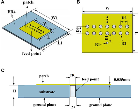
Figure 1 . The structural representation of the microstrip antenna. (A) The geometry of the proposed antenna, (B) The structure of the patch, (C) The cross-section view of the coaxial feed.
Theoretical Method
The structure proposed in [ 26 ] was used as a reference in this paper, but unlike the omnidirectional calculation in [ 26 ], single direction analysis was adopted. Figure 2 shows the geometry of photonic crystals and line sources. The impressed electric line source ( J 0 ( x,y )) located at the origin O of the x-y coordinate system is sandwiched between two photonic crystals, with a separation distance of t 1 . A common distance in the × direction is represented by h and the distance between cylinders is d1. The structure is arranged in a periodic array. The cylindrical elements on the same layer of the array should have the same material properties and dimensions, but those on difference layers do not necessarily have to be the same. a 1 is the radius of the cylinder and ε r1 is relative permittivity. The number of the photonic crystal layers above the X-axis is assumed to be N 1 . The Y-axis is analyzed in this paper.
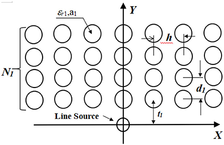
Figure 2 . Scheme of a localized Y line source embedded at the origin of the coordinate system of bounded two-dimensional photonic crystals.
The conventional Floquet mode expansion method cannot be directly used since the system concerned is not periodic. Therefore, the expression of the localized line source in terms of an infinite periodic array of linearly phased line sources in the spectral domain is considered using the identity [ 27 ]:
As shown in Figure 3 , photonic crystal layers located above the line source may be substituted by the plane boundary at y= t 1 . The said plane boundary is characterized by the generalized reflection and transmission matrices ( R ¯ N 1 - , F ¯ N 1 + ) , whose derivation was described in [ 29 ].
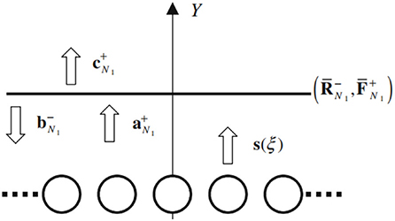
Figure 3 . Multiple scattering processes of space harmonics mainly radiated from the periodic array of line sources. The plane boundary characterized by the generalized reflection and transmission matrices R ¯ N 1 - , F ¯ N 1 + takes the place of the photonic crystals.
Then, by ray tracing the orthogonal space harmonics, the following relations are obtained:
The field E z ( x,y ) radiated from the localized line source (14) is obtained by plugging Formula (25) into Formula (15). A conventional numerical integration scheme is used to calculate the finite integral in Formula (15) with respect to the spectral parameter x. The singularities in the integrand are the poles that satisfy D(x) = 0, whose branch points meet κ ℓ (ξ) = 0. The poles correspond to the propagation constants of TE guided modes (usually limited within y < t 1 ). The far-zone fields are obtained from the spectral response for the propagating space harmonic components as follows:
where ρ = x 2 + y 2 and ϕ are the observation angles. The directive gain of the radiation G (ϕ) is given by:
The poles would degrade the radiation efficiency of the antenna and adjusting the lattice parameters of the photonic crystals could possibly eliminate the poles within the spectral range concerned. The pole removal can be easily achieved [ 28 ] by choosing the lattice parameters, enabling one of the eigenvalues η of the transfer matrix for space harmonics across the single layer of the array to satisfy |η|=1 in the far-zone radiation field. Without calculating the integration in Formula (15), the conventional asymptotic method [ 30 ] can be used to assess the contribution of the branch points. The photonic crystal array structure can significantly improve the radiation and gain of the antenna.
Technical Analysis
The through-hole structure is applied to the microstrip antenna in this paper. The equivalent circuit model of the structure with a single passing hole is shown in Figure S1 , where the passing hole generates the parasitic capacitance of C and parasitic inductance of L .
The outer diameter of the through-hole is d 1, the diameter of the power separation zone is d 2, the thickness of FR4 is H , ε r is the relative dielectric constant of the substrate, and d is the inner diameter of the through-hole.
The resonance generated between capacitance and inductance of a single hole or the resonance produced between holes will greatly affect the performance of the excitation antenna.
The series resonance formula is
The parallel resonance formula is
where f 0 is resonance frequency, ω 0 is resonance angular frequency, Q is the quality factor, and R is the resistance value.
The through-hole on the antenna designed in this paper has the following characteristics:
The resonant effect between the capacitance and the inductance can improve the reflection in the antenna design. Holes also resonate with each other. The air hole in the proposed design results in the corresponding reduction of substrate material, increasing the gain of the substrate. The influence of the array hole on parameters needs parameter optimization.
The equivalent circuit model of an ordinary rectangular microstrip antenna is shown in Figure S2A , where Z S is gap impedance and Z is impedance produced by the feeding point. The equivalent circuit of a microstrip antenna with drilling holes is shown in Figure S2B , where Z k is the impedance of the hole. Figure S2C shows the resonance produced by C and L . f 0 and f 1 are not the same resonance frequency.
The resonance frequency is expressed as:
Antenna Design
The through-hole array made from an ordinary rectangular microstrip antenna is applied to the patch of the antenna proposed in this study. Three gigahertz is taken as the reference frequency of the antenna. The antenna elements are simulated via High Frequency Simulator Structure (HFSS.15), and the return loss value is simulated by adjusting the size, spacing distance, and number of drilled holes.
First, seven through-holes are embedded into the patch according to the patch width. Then, the radius of the through-holes and the distance between holes are simulated and analyzed, as shown in Figures 4A,B . According to Figure 4A , the return loss shows little difference when R2 = 0.6 mm (23.5534 dB) and R2 = 1 mm (23.3522 dB). Thus, the radius of the holes on the designed antenna can take R2 = 1 mm. It can be seen from Figure 4B that the return loss effect is the best when D2 = 4 mm (23.3522 dB). When two rows of holes are drilled, the distance D3 should be adjusted and the value of D2 needs to be taken into account. The simulation results show that the return loss of the antenna is optimal at 2.9 GHz when D3 = 4, which is 24.3307 dB ( Figure 5A ).
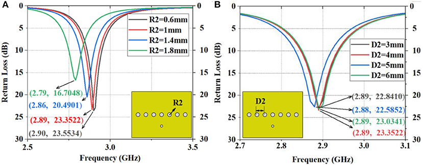
Figure 4 . The simulation of return loss of the antenna with one-line drilled holes on the patch center. (A) Different dimensions of R2, (B) Different dimensions of D2.
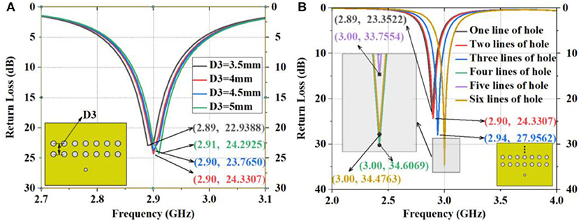
Figure 5 . The simulation of D3 and different lines of drilled holes. (A) Different dimensions of D3, (B) Return loss of antenna with 1, 2, 3, 4, 5, and 6 lines of holes.
Furthermore, 1, 2, 3, 4, 5, and 6 lines of holes are drilled on antennas with R2 = 1 mm, D2 = 4 mm, and D3 = 4 mm separately, and the resulting return loss of these six kinds of antennas are compared. As shown in Figure 5B , the return loss of antennas with one-line, two-line, three-line, four-line, five-line, and six-line holes is 23.3522 dB at 2.89 GHz, 24.3307 dB at 2.90 GHz, 27.9562 dB at 2.94 GHz, 34.6069 dB at 3.00 GHz, 33.7554 dB at 3.00 GHz, and 34.4763 dB at 3.00 GHz, respectively. The simulation results of the proposed antennas with multiple drilled holes are satisfying as the return loss reaches 34.6069 dB at 3 GHz ( Figure 5B ). D2, D3, and R2 of the four-line structure are optimized to eliminate uncertainties, as shown in Figures 6A , 7A . The compassion between antennas with and without apertures reveals that the return loss of the designed antenna is 10.3944 dB higher than that of the antenna without apertures ( Figure 7B ).
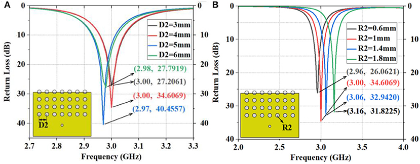
Figure 6 . The simulation of return loss of the antenna with four lines of drilled holes. (A) The different dimensions of R2, (B) The different dimensions of D2.
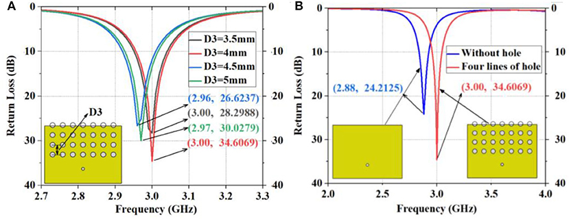
Figure 7 . The simulation of D3 as well as four-line and one-line holes. (A) The different dimensions of D3, (B) Comparison between the unperforated antenna and the antenna with four-row holes.
Structural Comparison
After deciding to drill 4-line through-holes on the antenna structure, structures with square, triangular, and spherical holes are compared ( Figure 8 ).
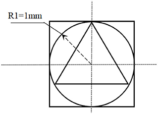
Figure 8 . The planar structure of the through hole, the square hole, and the triangular hole.
The comparison is made under unchanged D1, D2, and D3 in this paper, and only four rows are observed. In the one-line and two-line antennas ( Figure S3 ), the triangle structure has better return loss. As for the three-line and four-line antennas ( Figure S4 ), the through- hole structure has better return loss. This paper also compares the spherical holes with a radius of 0.8 mm ( Figure S5 ). Table 1 shows the comparison of return loss between perforated antennas and the unstructured antenna. From the above analysis, antenna 10 (the four-row through-hole structure) designed in this paper is the most ideal, which verifies the above design about through-hole structures.
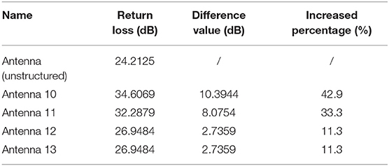
Table 1 . Comparison of perforated antennas with the unstructured antennas.
Simulation Index
The above antennas with four-row holes are compared under different R2, D2, and D3 values. Some of the four-row drilled holes are on the patch and others are on the substrate. The best return loss effect is achieved at 3 GHz when R2 = 1 mm, D2 = 4 mm, and D3 = 4 mm, so the antenna with four-row holes meeting these parameters is designed. This antenna is then compared with the unperforated antenna. As shown in Figure 7B , the return loss of the designed antenna increases the output by 42.9%, when compared to the unperforated antenna, which has an overall return loss of 24.2125 dB.
The horizontal current on the surface of the patch at the TM mode with a coaxial feed coupling structure is distributed forward (please see Figure S6 ). The distribution of current is such that the reflection of electromagnetic waves is fine.
The return loss of the simulated antenna is 34.6069 dB and the corresponding VSWR is 1.0379. When the return loss is 10 dB, it has a 90.2 MHz bandwidth. The parameters of the proposed antenna are shown in Table 2 .
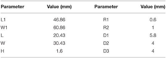
Table 2 . Detailed parameters of the proposed antenna.
As can be seen from the following figures, the simulation results of performance parameters of the designed antenna are satisfactory. Its gain is 4.9533 dBi at 3 GHz ( Figure S8B ), and its input impedance is about 50 Ω at 3 GHz ( Figure S9B ). For other simulation indicators, please see the figures in the Supplementary Materials .
Measurement
Precision machining and measurements of the four-row aperture structure designed in this paper were performed. The designed antenna was processed and tested using network analyzers (CETC41, AV3629A) in a 7 × 4 × 3 m rectangular microwave darkroom in the School of Electronic Engineering of Xidian University. Before the test, the most classic two-port system error calibrator, TOSM (through, open, short, match), also known as SOLT, was used for network analyzer calibration. Before the far-field test, the tester dealt with the test environment and equipment, including instrument calibration, cable loss zeroing, turntable debugging, etc. The 50 Ω SMA connector was used for back-feed at D1 from the center of the patch. To verify the results of the simulated design, a photo of the proposed antenna prototype was taken, and its return loss was simulated and measured ( Figure 9 ). The patch is made from copper, and the antenna surface is coated with tin to prevent oxidation. Table 3 shows the simulated and measured performance parameters of the proposed antenna with four-row holes. The measured 2-D radiation patterns (E-plane and H-plane) at 2.90, 2.95, and 3 GHz are shown in Figure 10 . The simulated and measured peak gains are about 4.95 dB at 3 GHz and about 4.88 dB at 2.95 GHz, respectively. Figure 11 shows the relationship between gain and frequency when both angles are zero. The simulation and measurement results of the antenna are basically identical. According to Table 4 , the parameter improvement in this paper is effective.
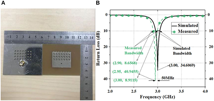
Figure 9. (A) The photo of front and back of the designed antenna; (B) simulation and measurement data of the designed antenna.
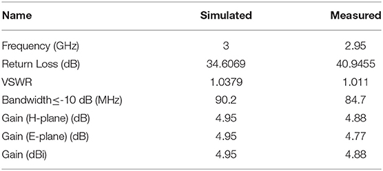
Table 3 . Simulation and measurement results of the proposed antenna with four-line holes.

Figure 10 . Measured 2-D radiation patterns at (A) 2.90GHz, (B) 2.95GHz, and (C) 3GHz (E-plane and H-plane).
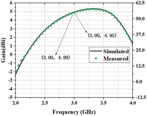
Figure 11 . Measured radiation gain of the proposed antenna.
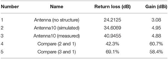
Table 4 . The comparison of return loss and gain.
As shown in Figure 9B , the difference between the measured and the simulated data is 50 MHz, which may be caused by a number of reasons. First, there are some errors between simulation and measurement. In general, the resonance frequency of the antenna after processing will be reduced, so it may lead to this situation. The HFSS software used for simulation in this study could be another reason. The method of selecting the feed and establishing the model by HFSS may be influencing factors. Third, the antenna processing accuracy, the feed welding during the test, the test cable loss in the antenna measurement, and the antenna test environment could also possibly result in the difference between the measured and the simulated data.
The process of antenna designing is subject to theoretical analysis, technical analysis, antenna design, antenna comparison, processing, and testing. This paper tries to achieve the design through theory discovery and software testing. The achieved return loss of the design is 69.1% higher than that of the antenna without holes and 18.3% higher than that of the simulated antenna. The gain increase of 58.4% is relatively non-porous. The results of this study suggest that a 4 × 7 array through-hole structure can improve the gain and radiation of microstrip antennas and can be realized based on the line source analysis and parameter optimization by using ANSYS HFSS. The simulation results are consistent with the experimental ones, even though there are some errors for the test frequency.
Innovations are made in the following four aspects: structure, theory, design optimization, and metrics improvement. First, in terms of structure, a 4 × 7 array through-hole structure is used to integrate the functions of photonic crystal and microstrip antennas. Second, theoretical analysis finds that the line source of the design structure, i.e., the 4 × 7 array hole, is different from the reference line source. The line source in a semicircle direction is also analyzed, with the corresponding formula deduced. The photonic crystal array structure can obviously improve the radiation and gain. Third, the structural design and optimization is investigated. The single-, double-, three-, four-, five-, and six-row holes are compared, and the hole spacing is explored. After design and optimization, the optimal scheme is finally determined for theoretical analysis and verification. Fourth, to improve the metrics, the 4 × 7 array structure is compared with a structure without holes. It is obvious that the return loss increases substantially. section Structural Comparison makes comparisons between several structures, which reveal that antenna 10, namely the 4 × 7 array structure, can deliver the best outcomes.
This paper promotes the research of photonic crystals and antennas and may offer help to researchers in the in-depth mining of the array hole structure in the future. This research also has some limitations. For instance, its bandwidth is not wide enough, but this issue will be improved in the future. The materials used to fabricate the prototype are low-cost, and the antenna is small in size, with easy heat dissipation and high mechanical strength. The simple structure can facilitate manufacturing and integration with other circuits. The wiring can also pass through the holes. The antenna designed in this paper can be used in the frequency band of radio navigation systems and positioning systems.
Data Availability Statement
The raw data supporting the conclusions of this article will be made available by the authors, without undue reservation, to any qualified researcher.
Author Contributions
All authors listed have made a substantial, direct and intellectual contribution to the work, and approved it for publication.
The authors would like to thank the National Natural Science Foundation of China and High-level talents program of Nanjing Forestry University for financially supporting this research under Contract Nos. 31170668 and 163070694.
Conflict of Interest
The authors declare that the research was conducted in the absence of any commercial or financial relationships that could be construed as a potential conflict of interest.
Supplementary Material
The Supplementary Material for this article can be found online at: https://www.frontiersin.org/articles/10.3389/fphy.2020.00290/full#supplementary-material
1. Shackelford A, Lee KF, Chatterjee D, Guo YX, Luk KM, Chair R. Small-size wide-bandwidth microstrip patch antennas. In: IEEE Antennas and Propagation Society International Symposium . USNC/URSI (2001). p. 86–9.
Google Scholar
2. Balanis CA. Antenna Theory-Analysis and Design . Hoboken, NJ: John Wiley & Sons, Inc. (2005).
3. Pozar DM. Microstrip antennas and arrays on chiral substrates. IEEE Trans Antennas Propagat. (2001) 40 :86–9. doi: 10.1109/8.182462
CrossRef Full Text | Google Scholar
4. Lee KF, Luk KM. Microstrip Patch Antennas. London: Imperial College Press (2011) doi: 10.1142/p669
5. Wang L, Tong J, Li Y. River Chief System (RCS): an experiment on cross-sectoral coordination of watershed governance. Front Environ Sci Eng. (2019) 13 :1–3. doi: 10.1007/s11783-019-1157-9
6. Chen C, Guo Y, Wang H. Wideband symmetrical cross-shaped probe dual-beam microstrip patch antenna. IEEE Antennas Wirel Propag Lett. (2015) 14 :622–5. doi: 10.1109/LAWP.2014.2375371
7. Liu S, Qi S, Wu W, Fang D. Single-feed dual-band single/dual beam u-slot antenna for wireless communication application. IEEE Trans Antennas Propagat. (2015) 63 :3759–64. doi: 10.1109/TAP.2015.2438331
8. Carver K, Mink J. Microstrip antenna technology. IEEE Trans Antennas Propagat. (1981) 29 :2–24. doi: 10.1109/TAP.1981.1142523
9. Lyu B, Yang Z, Gui G. Non-orthogonal multiple access in wireless powered communication networks with SIC constraints. IEICE Trans Commun. (2017) E101-B :1094–101. doi: 10.1587/transcom.2017EBP3179
10. Wang L, Jiang F, Yuan Z, Yang J, Gui G, Sari H. Mode division multiple access: a new scheme based on orbital angular momentum in millimetre wave communications for fifth generation. IET Commun. (2018) 12 :1416–21. doi: 10.1049/iet-com.2017.1182
11. Chakraborty U, Kundu A, Chowdhury SK, Bhattacharjee AK. Compact dual-band microstrip antenna for IEEE 802.11a WLAN application. IEEE Antennas Wirel Propag Lett. (2014) 13 :407–10. doi: 10.1109/LAWP.2014.2307005
12. Pourahmadazar J, Ghobadi C, Nourinia J, Felegari N, Shirzad H. Broadband CPW-Fed circularly polarized square slot antenna with Inverted-L strips for UWB applications. IEEE Antennas Wirel Propagat Lett. (2011) 10 :369–72. doi: 10.1109/LAWP.2011.2147271
13. Islam S, Latrach M. Design construction and testing of a compact size patch antenna for RFID applications. Microwave Opti Technol Lett. (2013) 55 :2920–5. doi: 10.1002/mop.27971
14. Wang W, Meng L, Ji R, Wang Z, Gao J, Liu Y, et al. A cpw-fed dual-beam shorted-patch antenna. IEICE Electron Express. (2018) 15 :1–6. doi: 10.1587/elex.15.20180100
15. Shimizu N, Nagatsuma T. Photodiode-integrated microstrip antenna array for subterahertz radiation. IEEE Photonics Technol Lett. (2006) 18 :743–5. doi: 10.1109/LPT.2006.871131
16. Mahdia RAH, Taha SMR. Miniaturization of rectangular microstrip patch antenna using topology optimized metamaterial. IEICE Electronic Express. (2017) 14 :1–6. doi: 10.1587/elex.14.20170787
17. Boutayeb H, Denidni TA. Gain enhancement of a microstrip patch antenna using a cylindrical electromagnetic crystal substrate. IEEE Trans Antennas Propagat. (2007) 55 :3140–5. doi: 10.1109/TAP.2007.908818
18. Agi K, Mojahedi M, Minhas B, Schamiloglu E. The effects of an electromagnetic crystal substrate on a microstrip patch antenna. IEEE Trans Antennas Propagat. (2002) 50 :451–6. doi: 10.1109/TAP.2002.1003380
19. Lechen Y, Xiuli Z, Li H, Fu K, Zhang B. Ultra-wideband multi-frequency terahertz square microstrip patch antenna on hybrid photonic crystal substrate. J Comput Theor Nanosci. (2013) 10 :968–73. doi: 10.1166/jctn.2013.2794
20. Zhu XL, Liu B. Wang X. Design of compact mems antenna based on photonic crystal structure. J Elect Eng Technol . (2019) 14 :2085–90. doi: 10.1007/s42835-019-00233-7
21. Rodriguez-Berral R, Mesa F, Jackson DR. Excitation of an infinite microstrip line with a vertical coaxial feed. IEEE Trans Microwave Theor Techniq. (2008) 56 :1638–48. doi: 10.1109/TMTT.2008.925568
22. El-Raouf HEA, Prakash VVS, Yeo J, Mittra R. FDTD simulation of a microstrip phased array with a coaxial feed. IEE Proc Microwaves Antennas Propagat. (2004) 151 :193–8. doi: 10.1049/ip-map:20040269
23. Stutzke NA, Filipovic DS. Four-arm 2nd- mode slot spiral antenna with simple single-port feed. IEEE Antennas Wirel Propag Lett. (2005) 4 :213–6. doi: 10.1109/LAWP.2005.851006
24. Pregla R. The analysis of general axially symmetric antennas with a coaxial feed line by the method of lines. IEEE Trans Antennas Propagat. (1998) 46 :1433–43. doi: 10.1109/8.725274
25. Lee CS, Nalbandian V. Planar circularly polarized microstrip antenna with a single feed. IEEE Trans Antennas Propagat. (1999) 47 :1005–7. doi: 10.1109/8.777124
26. Jandieri V, Yasumoto K, Toyama H. Radiation from a line source placed in two-dimensional photonic crystals. Int J Infrared Millimeter Waves. (2007) 28 :1161–73. doi: 10.1007/s10762-007-9295-8
27. Lighthill MJ. Introduction to Fourier Analysis and Generalized Functions . Cambridge University Press. doi: 10.1017/CBO9781139171427
28. Yasumoto K, Toyama H, Kushta T. Accurate analysis of two-dimensional electromagnetic scattering from multilayered periodic arrays of circular cylinders using lattice sums technique. IEEE Trans Antennas Propag. (2004) 52 :2603–11. doi: 10.1109/TAP.2004.834440
29. Yasumoto K, Jia H. Modeling of pfshotonic crystals by layered periodic arrays of cylinders. Electromag Theor Appl Photonic Cryst. (2005) 3 :123–90. doi: 10.1201/9781315221106-3
30. Brekhovskikh LM. Waves in Layered Media . 2nd ed. Oxford: Academic Press (1980).
Keywords: line source, microstrip antenna, gain, return loss, through-hole
Citation: Ding Z, Zhang D and Ma C (2020) A Study of a Microstrip Patch Antenna With a Drilled Through-Holes Array Structure Based on the Line Source Analysis Method. Front. Phys. 8:290. doi: 10.3389/fphy.2020.00290
Received: 18 January 2020; Accepted: 26 June 2020; Published: 14 September 2020.
Reviewed by:
Copyright © 2020 Ding, Zhang and Ma. This is an open-access article distributed under the terms of the Creative Commons Attribution License (CC BY) . The use, distribution or reproduction in other forums is permitted, provided the original author(s) and the copyright owner(s) are credited and that the original publication in this journal is cited, in accordance with accepted academic practice. No use, distribution or reproduction is permitted which does not comply with these terms.
*Correspondence: Dan Zhang, zhangdan@njfu.edu.cn
This article is part of the Research Topic
Recent Progress in Surface Electromagnetic Modes
Design and Simulation of Microstrip Patch Antenna for Wireless Communication Systems
Ieee account.
- Change Username/Password
- Update Address
Purchase Details
- Payment Options
- Order History
- View Purchased Documents
Profile Information
- Communications Preferences
- Profession and Education
- Technical Interests
- US & Canada: +1 800 678 4333
- Worldwide: +1 732 981 0060
- Contact & Support
- About IEEE Xplore
- Accessibility
- Terms of Use
- Nondiscrimination Policy
- Privacy & Opting Out of Cookies
A not-for-profit organization, IEEE is the world's largest technical professional organization dedicated to advancing technology for the benefit of humanity. © Copyright 2024 IEEE - All rights reserved. Use of this web site signifies your agreement to the terms and conditions.

- Previous Article
- Next Article

Design of a new microstrip patch antenna at 60GHz for 5G
- Article contents
- Figures & tables
- Supplementary Data
- Peer Review
- Reprints and Permissions
- Cite Icon Cite
- Search Site
Salah-Eddine Didi , Imane Halkhams , Mohammed Fattah , Younes Balboul , Said Mazer , Moulhime El Bekkali; Design of a new microstrip patch antenna at 60GHz for 5G. AIP Conf. Proc. 11 July 2023; 2814 (1): 030013. https://doi.org/10.1063/5.0148874
Download citation file:
- Ris (Zotero)
- Reference Manager
This paper studies and designs a new microstrip patch antenna with a rectangle geometry to which a T-shaped part is subtracted. This part allows both to reduce the dimensions and optimize this antenna’s performance. This device ensures better performance quality related to the operation of the 5G Wireless Communication System. The design is made by using the microstrip line feed technique. This kind of feed provides excellent bandwidth, is simple to design, and has low parasitic radiation. The distance between the feed line and the patch can adapt to the antenna impedance. In addition, the design and the simulations of the proposed antenna perform using 5G millimeter band HFSS simulation software, and its operating frequency is 60 GHz. The proposed antenna is implemented on the so-called Rogers RTduroid 5880 substrate, with a relative permittivity of 2.2, a thickness of h=0.16mm, and a loss tangent of 0.0009. The profile for this antenna is 2mm×1.6mm×0.16mm. The simulation results acquired during this research are presented as follows: Reflection coefficient:-30.99dB, Standing wave ratio: 1.058, Bandwidth: 1.91GHz (59.05GHz-60.96GHz), Gain: 8.3dB, Radiated power: 10.016dBm, Accepted power: 9.99dBm, Incident power: 10dBm, Efficiency: 99.74%. Indeed, it is clear that the characteristics offered by this proposed antenna are better than those of other works announced in the last scientific editions. As a result, this antenna is likely to become an important competitor for 5G wireless communication applications.
Sign in via your Institution
Citing articles via, publish with us - request a quote.

Sign up for alerts
- Online ISSN 1551-7616
- Print ISSN 0094-243X
- For Researchers
- For Librarians
- For Advertisers
- Our Publishing Partners
- Physics Today
- Conference Proceedings
- Special Topics
pubs.aip.org
- Privacy Policy
- Terms of Use
Connect with AIP Publishing
This feature is available to subscribers only.
Sign In or Create an Account

Proceedings of 3rd International Conference on Computing Informatics and Networks pp 485–494 Cite as
Performance Evaluation of Rectangular Microstrip Patch Antenna based on Defected Ground Structures
- Pawar Umesh Ankush ORCID: orcid.org/0000-0003-0149-0446 12 ,
- Abhijyoti Ghosh ORCID: orcid.org/0000-0001-9011-7998 13 ,
- Lourembam Lolit Kumar Singh ORCID: orcid.org/0000-0003-0875-5427 13 &
- Sudipta Chattopadhyay ORCID: orcid.org/0000-0001-8935-2990 13
- Conference paper
- First Online: 15 March 2021
694 Accesses
Part of the book series: Lecture Notes in Networks and Systems ((LNNS,volume 167))
A rare and novel comparative study of different defected ground structure integrated rectangular microstrip antenna has been presented in this paper. The defects are placed in such a way to get a clear insight into the concept behind improvements in antenna parameters while compulsorily maintaining the polarization purity by the use of regular defects that are in increasing order of polygons. Different structures of defected ground can give polarization purity of 22–28 dB and gain in the range of at least 8.5–9.1 dBi is suggested herewith. Both the requirements are inescapable being fundamental in nature to the field of polarimetric radars even though various compensating methods are available.
Rectangular microstrip patch antenna
Defected ground structure
Cross-polarization
This is a preview of subscription content, log in via an institution .
Buying options
- Available as PDF
- Read on any device
- Instant download
- Own it forever
- Available as EPUB and PDF
- Compact, lightweight edition
- Dispatched in 3 to 5 business days
- Free shipping worldwide - see info
- Durable hardcover edition
Tax calculation will be finalised at checkout
Purchases are for personal use only
Abbreviations
Co-polarized
Defected patch surface
Microstrip patch antenna
Perfect electric conducting
Perfect magnetic conducting
Kumar G, Ray KP (2003) Broadband microstrip antennas. Artech House, Norwood, USA
Google Scholar
Guha D, Antar YMM (2011) Microstrip and printed antennas-new trends, techniques and applications. John Wiley, U.K.
Garg R, Bhartia P, Bahl I, Ittipiboon A (2001) Microstrip Antenna design handbook. Artech House, Norwood, USA
Islam MT, Shakib MN, Misran N (2009) Design analysis of high gain wideband l-probe fed microstrip patch antenna. Prog Electromag Res 95:397–407
Article Google Scholar
Yang F, Zhang X, Ye X, Samii YR (2001) Wide-band E-shaped patch antennas for wireless communications. IEEE Trans Ant And Prop 49(7):1094–1100
Sharma SK, Shafai L (2009) Performance of a novel Ψ-shape microstrip patch antenna with wide bandwidth. IEEE Ant Wireless Prop Lett 8:468–471
Jaggard DL (1990) On fractal electrodynamics. In: Kritikos HN, Jaggard DL (eds) Recent advances in electromagnetics theory. Springer-Verlag, New York, pp 183–224
Jaggard DL (1991) Fractal electrodynamics and modeling. In: Bertoni HL, Felsen LB (eds) Direction in electromagnetics wave modeling. Springer, Boston, pp 235–283
Jaggard DL (1995) Fractal electrodynamics: wave interactions with discretely self-similar structures. In: Baum C, Kritikos H (eds) Electromagnetic symmetry. Taylor & Francis, Washington, DC, pp 231–281
Werner DH (1955) An overview of fractal electrodynamics research. In: Proceedings of the 11th annual review of progress in applied computational electromagnetics (ACES), vol 2, pp 964–969
Jaggard DL (1997) Fractal electrodynamics: from super antennas to superlattices. In: Levy VJ, Lutton E, Tricot C (eds) Fractal in engineering. Springer, London, pp 204–221
Chapter Google Scholar
Petosa A, Ittipiboon A, Gagnon N (1999) Suppression of unwanted probe radiation in wide band probe-fed microstrip patches. Electron Lett 35(5):355–357
Li P, Lai HW, Luk KM, Lau KL (2004) A wideband patch antenna with cross-polarization suppression. IEEE Antennas Wireless Propag Lett 3:211–214
Wong KL, Tang CL, Chiou JY (2002) Broad-band probe-fed patch antenna with a W-shaped ground plane. IEEE Trans Antennas Propag 50:827–831
Hsu WH, Wong KL (2002) Broad-band probe-fed patch antenna with a U-shaped ground plane for cross-polarization reduction. IEEE Trans Antennas Propag 50:352–355
Jackson DR, Alexopoulos NG (1991) Simple approximate formulas for input resistance, bandwidth, and efficiency of a resonant rectangular patch. IEEE Trans Antennas Propag 39(3):407–410
Ghosh A, Basu B (2019) Triangular slotted ground plane: a key to realize high gain, cross-polarization free microstrip antenna with improved bandwidth. Turk J Electr Eng Comput Sci 27:1559–1570
Nath AK, Singh LLK, Chattopadhyay S, Ghosh A (2020) Study of polarization purity of rectangular microstrip antenna integrated with pentagon dumbelled shaped defected ground structure. In: Dawn S, Balas VE, Esposito A, Gope S (eds) International conference on innovations in modern science and technology 2019, LAIS, vol 12. Springer, Cham, pp 484–492
Pawar UA, Chakraborty S, Singh LLK, Chattopadhyay S (2018) Application of defected ground structure for augmenting high-gain ultra-wide bandwidth from rectangular microstrip antenna. Electromagnetics 38:123–133
Pawar UA, Ghosh A, Singh LLK, Chattopadhyay S (2019) Application of defected ground structure for stable gain with ultrawide bandwidth. In: Bera R, Sarkar S, Singh O, Saikia H (eds) International conference in communication, devices and networking 2018, LNEE, vol 537,. Springer, Singapore, pp 141–149
Ghosh D, Ghosh SK, Nandi S, Chakraborty D, Anand R, Raj R, Ghosh A (2014) Physical and quantitative analysis of compact rectangular microstrip antenna with shorted non-radiating edges for reduced cross-polarized radiation using modified cavity model. IEEE Antennas Propag Mag 56(4):61–72
Ghosh A, Ghosh D, Chattopadhyay S, Singh LLK (2015) Rectangular microstrip antenna on slot type defected ground for reduced cross polarized radiation. IEEE Antennas Wireless Propag Lett 14:321–324
Ghosh A, Chakraborty S, Chattopadhyay S, Nandi A, Basu B (2016) Rectangular microstrip antenna with dumbbell shaped defected ground structure for improved cross polarized radiation in wide elevation angle and its theoretical analysis. IET Microw Antennas Propag 10(1):68–78
Chattopadhyay S, Chakraborty S (2018) A physical insight into the influence of dominant mode of rectangular microstrip antenna on its cross-polarization characteristics and its improvement with T-shaped microstrip antenna. IEEE Access 6:3594–3602
HFSS High frequency structure simulator, Ver. 14, Ansoft Corp., USA
Download references
Author information
Authors and affiliations.
Indian Army, New Delhi, India
Pawar Umesh Ankush
Department of Electronics and Communication Engineering, Mizoram University, Aizawl, Mizoram, India
Abhijyoti Ghosh, Lourembam Lolit Kumar Singh & Sudipta Chattopadhyay
You can also search for this author in PubMed Google Scholar
Corresponding author
Correspondence to Abhijyoti Ghosh .
Editor information
Editors and affiliations.
Scientific Network for Innovation and Research Excellence, Machine Intelligence Research Labs (MIR Labs), Auburn, WA, USA
Ajith Abraham
Tijuana Institute of Technology, Tijuana, Mexico
Oscar Castillo
Bhagwan Parshuram Institute of Technology, New Delhi, India
Deepali Virmani
Rights and permissions
Reprints and permissions
Copyright information
© 2021 The Author(s), under exclusive license to Springer Nature Singapore Pte Ltd.
About this paper
Cite this paper.
Umesh Ankush, P., Ghosh, A., Lolit Kumar Singh, L., Chattopadhyay, S. (2021). Performance Evaluation of Rectangular Microstrip Patch Antenna based on Defected Ground Structures. In: Abraham, A., Castillo, O., Virmani, D. (eds) Proceedings of 3rd International Conference on Computing Informatics and Networks. Lecture Notes in Networks and Systems, vol 167. Springer, Singapore. https://doi.org/10.1007/978-981-15-9712-1_41
Download citation
DOI : https://doi.org/10.1007/978-981-15-9712-1_41
Published : 15 March 2021
Publisher Name : Springer, Singapore
Print ISBN : 978-981-15-9711-4
Online ISBN : 978-981-15-9712-1
eBook Packages : Engineering Engineering (R0)
Share this paper
Anyone you share the following link with will be able to read this content:
Sorry, a shareable link is not currently available for this article.
Provided by the Springer Nature SharedIt content-sharing initiative
- Publish with us
Policies and ethics
- Find a journal
- Track your research

Search form
Design and study of a microstrip patch antenna for gps application.
Mouloud Ayad * | Kamel Saoudi | Turki E.A. Alharbi | Mohammed S. Alzaidi | Mourad Benziane | Souhil Mouassa | Sherif S.M. Ghoneim
© 2022 IIETA. This article is published by IIETA and is licensed under the CC BY 4.0 license ( http://creativecommons.org/licenses/by/4.0/ ).
OPEN ACCESS
A microstrip patch antenna for Global Positioning System (GPS) application is presented in this study. It has a rectangular shape with two notched slots. The notched slots are introduced to improve the adaptation between the microstrip line and the antenna. The antenna was designed and simulated by CST using FR-4 material as the substrate with relative permittivity of 4.3. The proposed microstrip antenna is designed to operate in the GPS band frequency from 1.555 GHz to 1.595 GHz. The performance analysis of the proposed antennas has been carried out in terms of return loss (dB), gain (dB), and VSWR.
microstrip patch antenna, GPS, return loss, VSWR
Telecommunications systems are very widely present in our current smart lifestyles. The Global Positioning System (GPS) is one of these systems. It is a satellite geographic positioning system used by various navigation systems. These localization systems have become essential to the tremendous demands for new services and applications in multiple civil and military domains. GPS is very widely used in several domains, such as in monitoring systems [1-6], intelligent systems [7-9], power management [10], and other applications. Moreover, GPS can provide real-time location information for an unlimited number of users. A satellite navigation system allows users equipped with a receiver to calculate and determine their position at any place on earth from the estimation of the distance which separates them from a minimum number of satellites. When we talk about GPS, we must systematically and specifically consider the equipment used to provide location. However, the GPS is not limited to this type of instrument, as it consists of three different elements called segments or sectors. The first segment of satellites is called the space segment. The second segment comprising the control station is called the control segment, and the last segment corresponding to the GPS receiver is called the user segment. In user equipment, we find the essential element of transmission. In the GPS systems, the antennas do the emission and reception of the data. These antennas are used at the reception level and are generally placed in land vehicles, aircraft, and ships to precisely locate their positions. It has advantageous characteristics (wide frequency band, security, and high speed). The antennas aim to perfect and improve several performances for all wireless communication systems [11-14]. Therefore, the antenna is a crucial element for coupling the device and the propagation medium. Hence, the design and proposition of a microstrip patch antenna for GPS application is a vital task.
Several microstrip patch antenna are presented in the literature for GPS applications [15-23].
Supriya and Rajendran [17] proposed an antenna for a GPS system based on an open-loop resonator, a split rectangular slot, and a stub at the non-radiating edge to generate three operating bands. Awais et al. [18] use four-element antenna array for the proposed antenna for a navigation satellite system. It is an assembled of 4 single patch antenna elements. Based on a circularly polarized dielectric resonator, Sharma et al. [19] present an antenna for GPS application that operates at 1.56 GHz. Lee et al. [20] proposed a patch antenna with a metallic reflector. This antenna is designed for GPS applications and operates at 1.575 GHz. The occupied volume by the antenna and the reflector is very extensive. With the addition of an artificial magnetic conductor plane, the proposed antenna [21] operates with a dual-band at 1.575 GHz for GPS and at 2.45 GHz for WLAN applications. Another antenna that operates in dual bands for GPS application is proposed by Zhong et al. [22]. The proposed antenna consists of two patches to generate two bands. Another antenna is proposed by Pourbagher et al. [23] with circular polarization. The structure of the antenna is composed of two orthogonally dipoles.
The main challenges in these proposed antennas are volume and occupied areas. Therefore, this paper aims to design, simulate, and analyze an antenna with a reduced volume destined for GPS application.
The rest of this paper is organized as follows: In section 2, the antenna design steps are presented. The results and discussion are given in Section 3. Finally, the last section provides the conclusion.
This part is devoted to studying the influence of the different parameters on the reflection coefficient S11 and the VSWR. A parametric study was conducted to obtain an effective and optimized final structure to understand the various parameters' influence. We use FR-4 material as the substrate, usually with relative permittivity equal to 4.3. The parameters to modify are the length (Lp) and the width (Wp) of the patch, the width of the microstrip line (Wf), the width (gpf), and the length (fi) of the notch, and the thickness of the substrate (hs). The proposed antenna structure and detailed configurations are illustrated in Figure 1.

Figure 1. Antenna structure
This part will present the structure and simulation results of the patch antenna of rectangular shape fed by the microstrip line, and this is for a GPS application in a frequency band of value 1.575 GHz [20-23].
The sections below present the evolution steps of the design of the proposed antenna according to the following forms: the ground plane, the substrate, and the radiating patch. For this antenna, we have chosen a power supply by microstrip line. The parametric study justifies this choice to improve the GPS frequency band of [1.555-1.595] GHz.
2.1 Influence of the (Lp) patch length
The length of the patch has a vital role in determining the resonant frequency. This part will allow us to see the variation in the size of the patch (Lp). The results obtained are represented the Table 1.
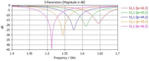
Figure 2. Influence of length (lp) by the contribution of reflection coefficient (S11)
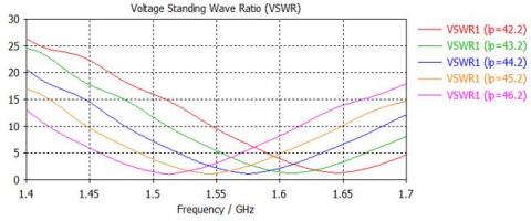
Figure 3. Influence of the length (lp) by the standing wave ratio VSWR contribution
Figure 2 and Figure 3 show the results of the influence of the length of the patch (Lp) by input reflection coefficient (S11) and the VSWR.
In Figure 3, we note that the length of the patch mainly affects the matching of the antenna. The patch size (lp) reduction leads to an increase in the resonant frequency and bandwidth. Also, from Figure 3 and Table 1, we observed that for all changes in length that we made, the VSWR remains less than 2 (VSWR ≤ 2), therefore, we can conclude that the length lp3= 44.2 mm is the best to improve the frequency band [1.555 to 1.595] GHz.
2.2 Influence of patch width Wp
The patch's parameters (the length (Lp), the permittivity (εr), and the height (hs) of the substrate) are fixed during the study. However, the parameter relating to the width of the patch varies continuously.
The results obtained are shown in Table 2.
The influence of length (Wp) by the contribution of reflection coefficient (S11) is given in Figure 4.
In the case of a variation in the width of the patch, presented in Table 2 and Figure 5, show us that the bandwidth and the resonant frequency register minor downward variations while the reflection coefficient varies.
According to Figure 5, we notice that the VSWR gives us values ≤ 2, so we conclude that the width wp3 = 58.5 mm is the best width to improve the frequency band [1.555-1.595] GHz.
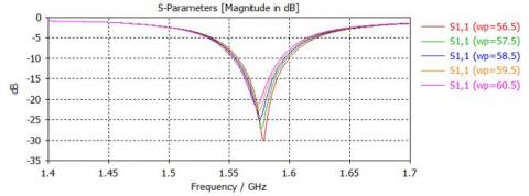
Figure 4. Influence of length (Wp) by the contribution of reflection coefficient (S11)
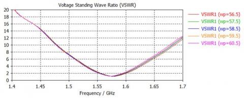
Figure 5. Influence of the width (Wp) by the standing wave ratio VSWR contribution
2.3 Influence of the thickness (hs) of the substrate
We will fix all the antenna parameters and change the value of the thickness (hs) of the substrate. The results obtained are identified in Table 3.
Figure 6 below clearly shows the variation of the thickness (hs) of the substrate on the parameter S11.
Table 1. Study the variation of the patch length (lp) on the antenna
Table 2. Study the variation of the patch width (wp) on the antenna
Table 3. Study the variation of the substrate thickness (hs) on the antenna
Table 4. Study the variation of the microstrip line width (wf) on the antenna
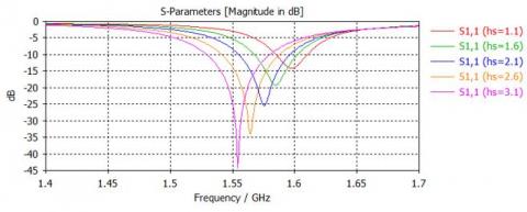
Figure 6. Influence of thickness (hs) by the contribution of reflection coefficient (S11)
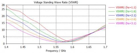
Figure 7. Influence of the thickness (hs) by the standing wave ratio VSWR contribution
Figure 6 shows that the bandwidth increases as the substrate thickness (hs) increase. Moreover, the resonant frequency decreases as the thickness (hs) grow. Therefore, the resonant frequency is inversely proportional to the substrate thickness (hs). On the other hand, the bandwidth is symmetrical to the thickness (hs) of the substrate.
The influence of the thickness (hs) of the substrate on VSWR is presented in Figure 7.
According to Figure 7 and the results of Table 3 obtained, the different thicknesses of the substrate (hs), the VSWR ≤ 2, so we conclude that the thickness hs3= 2.1 mm is the best to improve the frequency band [1.555-1.95] GHz.
2.4 Influence of the width of the micro ribbon line wf
By changing the width of the microstrip line (wf), we distinguish the different variables according to Table 4.
The influence of different widths line (wf) of the microstrip on the reflection coefficient (S11), and the VSWR are presented in Figures 8 and 9.
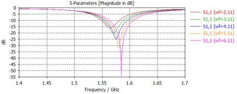
Figure 8. Influence of width (wf) by the contribution of reflection coefficient (S11)
According to the data in Table 4 and Figure 9, we note that with each increase in the microstrip line width (wf), the resonance frequency and bandwidth increase while the reflection coefficient changes.
According to Figure 9, we observe that for all the widths of the micro-strip line wf the VSWR ≤ 2, according to these results, we conclude that the width wf3= 4.11mm is the best to perfect the frequency band [1.555–1.595] GHz.
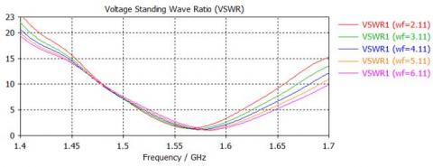
Figure 9. Influence of the width (wf) by the standing wave ratio VSWR contribution
2.5 Influence of the (gpf) width of the notch
We have found in the literature that adding a notch makes it better to fit the antenna fed by the microstrip line. The following Table 5 summarizes all of the notch width change results.
Table 5. Study the variation of the width of the notched (gpf) on the antenna
The notch width variation (gpf), in terms of the reflection coefficient S11 and VSWR, are shown in Figure 10 and Figure 11, respectively.
From the analysis of Figure 10, we find that the width (gpf) of the notch, for small values, the bandwidth decreases with the stability of the resonant frequency. On the other hand, when the value of (gpf) is zero, the adaptation between the microstrip line and the antenna is weak.

Figure 10. Influence of width (gpf) by input reflection coefficient (S11)
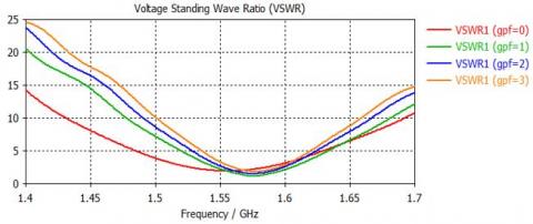
Figure 11. Influence of the (gpf) width by the standing wave ratio VSWR contribution
Figure 11 shows VSWR (dB) as frequency (GHz) function. Please note that our VSWR≤ 2 for all notch (gpf) widths used. Based on these results, we conclude that the width gpf2= 1 mm is better to improve the [1.555-1.595] GHz band.
2.6 Influence of the length (fi) of the notch
The notched band is recommended to improve the adaptation between the microstrip line and the antenna. The following table shows some results on the variation of the values of the notch length.
The next curve gives the results of the influence of the length (fi) of the notch concerning the reflection coefficient S11.
The curve above shows the results of the influence of the length (fi) of the notch concerning the VSWR.
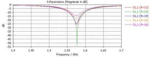
Figure 12. Influence of length (fi) by the contribution of reflection coefficient (S11)
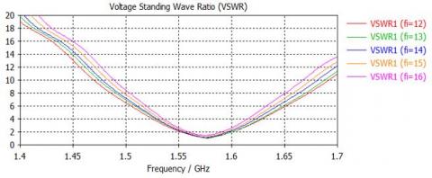
Figure 13. Influence of the length (fi) by the standing wave rate VSWR contribution
Table 6. Study the variation of the length of the notched (fi) on the antenna
Figure 12 indicates that the resonance frequency remains almost the same for different lengths with a very slight variation, while the level of S11 is varied.
On the other hand, through Figure 13 and Table 6, we noticed that by making all the changes related to the (gpf) length of the notch, the VSWR always remains less than or equal to 2 (VSWR≤2).
From the studies we have done, we note that for the resonant frequency equal to 1.575 GHz, we find that the impedance is Z = 50.7-0.31j, so we can say that when the fundamental part of impedance input reaches its maximum, the imaginary part vanishes.
We can deduce the final parameters to improve the frequency band; see Table 7 below.
After designing the antenna, we simulate the latter's operation, which was intended for the GPS application.
The results obtained by studying this antenna are represented in several parameters, the most important: the reflection coefficient (S11), VSWR, and the radiation pattern, which are shown in the figures below.
Figure 14 shows the result of the simulation of the reflection coefficient S11 (dB) as a function of frequency (GHz). We observed that the antenna showed a good adaptation in the band [1.555-1.595] GHz, so the reflection coefficient is less than -10dB, then the latter is the smallest at the resonance frequency of 1.575 GHz at - 24.804dB.
Figure 15 determines the result of the standing wave ratio VSWR as a function of frequency (GHz). The figure shows that VSWR ≤ 2 corresponds to S11 ≤ − 10 dB in the same frequency band (1.555-1.595) GHz.
CST software makes it possible to visualize the radiation diagram in gain and directivity after the simulation (Figures 16 (a) and (b)). We observe that the radiation diagram of this antenna is oriented in the Z direction. We note that the gain and directivity are positive when the antenna radiates on the 1.575 GHz frequency band.
Figure 17 shows the radiation patterns in two planes: E and H, for the antenna frequency, studied (1.575 GHz).
From Figure 17, the antenna radiates in the direction (θ= 0°). The angular widths are 96.9° and 71.9° in the E-plan and H-plane, respectively. The corresponding side lobe levels are -12.1 dB and -12.6 dB.
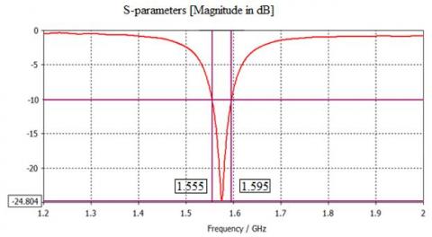
Figure 14. Reflection coefficient (S11) of the proposed antenna
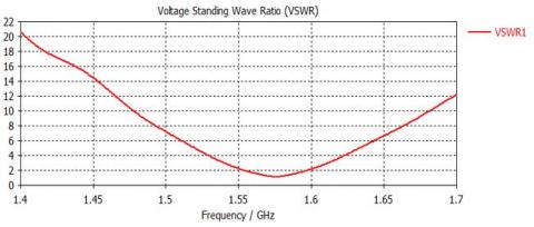
Figure 15. VSWR of the proposed antenna
Table 7. Size of the optimized antenna
Table 8. Comparison of the proposed antenna with related works
* The circular shape with D is the diameter (mm), and h is the thickness

Figure 16. 3D radiation patterns of proposed antenna
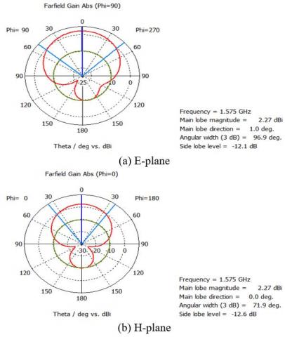
Figure 17. 2D gain radiation pattern
To give significance to the proposed antenna, a comparison with recently proposed antennas is necessary. The performance of the proposed antenna is compared with recently proposed antennas in the literature is given in Table 8.
The two sizes [19] are the antenna's size and the dielectric resonator. The two sizes are those of the antenna and the reflector [20].
According to Table 8, the proposed antenna has a good array area and good occupied volume.
A microstrip patch antenna has been proposed and investigated for GPS application. The proposed antenna has compact dimensions of 95×82×2.1 mm 3 . The antenna is designed to operate in the GPS band frequency from 1.555 GHz to 1.595 GHz and resonates at 1.575 GHz with a return loss of -24.804 dB. The material used for the substrate is FR-4, with relative permittivity of 4.3. The performance analysis of the proposed antennas has been tested by the obtained values of the return loss (dB), gain (dB), and VSWR. The obtained results verify the satisfactory performance of the proposed antenna for GPS application.
The following steps to deepen this study are the miniaturization of the antenna's dimensions in future work. In the second part, the antenna's operating frequency must be extended to multiband to support other ranges of applications.
This research was supported by the collaboration of University of Bouira, Algeria (PRFU N°: A10N01UN100120220001) and Taif University Researchers Supporting Project Number TURSP-2020/34, Taif University, Taif, Saudi Arabia.
[1] Zhang, C., Xue, W., Xin, Y. (2019). Design and application of an intelligent patrol algorithm for forest management and protection based on global positioning system. Ingénierie des Systèmes d'Information, 24(6): 597-602. https://doi.org/10.18280/isi.240606 [2] Bandyopadhyay, M., Mandal, N., Chattopadhyay, S., Roy, B. (2017). A novel GSM and GPS based vehicle security system. Advances in Modelling and Analysis D, 22(1): 62-76. https://doi.org/10.18280/ama_d.220105 [3] Plaza, J., Palacios, C., Abecia, J.A., Nieto, J., Sánchez-García, M., Sánchez, N. (2022). GPS monitoring reveals circadian rhythmicity in free-grazing sheep. Applied Animal Behaviour Science, 251: 105643. https://doi.org/10.1016/j.applanim.2022.105643 [4] Razin, M.R.G., Voosoghi, B. (2022). Modeling of precipitable water vapor from GPS observations using machine learning and tomography methods. Advances in Space Research, 69: 2671-2681. https://doi.org/10.1016/j.asr.2022.01.003 [5] Poliziani, C., Rupi, F., Schweizer, J. (2022). Traffic surveys and GPS traces to explore patterns in cyclist’s in-motion speeds. Transportation Research Procedia, 60: 410-417. https://doi.org/10.1016/j.trpro.2021.12.053 [6] Tran, Q.H., Fang, Y.M., Chou, T.Y., Hoang, T.V., Wang, C.T., Vu, V.T., Chen, M.H. (2022). Short-term traffic speed forecasting model for a parallel multi-lane arterial road using GPS-monitored data based on deep learning approach. Sustainability, 14(10): 6351. https://doi.org/10.3390/su14106351 [7] Hilal, H.A., Hilal, N.A., Hilal, T.A. (2022). Crowdsensing application on coalition game using GPS and IoT parking in smart cities. Procedia Computer Science, 201: 535-542. https://doi.org/10.1016/j.procs.2022.03.069 [8] Arshad, J., Rehman, A.U., Othman, M.T.B., Ahmad, M., Tariq, H.B., Khalid, M.A., Hamam, H. (2022). Deployment of wireless sensor network and IoT platform to implement an intelligent animal monitoring system. Sustainability, 14(10): 6249. https://doi.org/10.3390/su14106249 [9] Shi, Y., Yang, T., Zhang, S., Liu, L., Cui, Y. (2020). A Wi-Fi positioning system for material transport in greenhouses. Instrumentation Mesures Métrologies, 19(1): 65-72. https://doi.org/10.18280/i2m.190109 [10] Wei, X., Aman, M., Sikdar, B. (2021). Exploiting correlation among GPS signals to detect GPS spoofing in power grids. IEEE Transactions on Industry Applications, 58(1): 2022. https://doi.org/10.1109/TIA.2021.3131970 [11] El Yassini, A., Jallal, M.A, Ibnyaich, S., Zeroual, A., Chabaa, S. (2020). A miniaturized CPW-fed reconfigurable antenna with a single-dual band and an asymmetric ground plane for switchable band wireless applications. Traitement du Signal, 37(4): 633-638. https://doi.org/10.18280/ts.370412 [12] Gao, Y., Lu, H. (2019). A novel co-planar waveguide-fed direct current wide band printed dipole antenna. Traitement du Signal, 36(3): 253-257. https://doi.org/10.18280/ts.360308 [13] Farooq, U., Rather, G.M. (2019). Design and analysis of rectangular microstrip antenna (RMSA) for millimeter wave communication applications. Traitement du Signal, 36(5): 433-438. https://doi.org/10.18280/ts.360508 [14] Kumar, S., Dixit, A.S. (2021). A miniaturized CSRR loaded 2-element MIMO antenna for LTE band. Mathematical Modelling of Engineering Problems, 8(6): 984-988. https://doi.org/10.18280/mmep.080620 [15] Basit,A., Khattak, M.I., Sebak,R., Qazi, A., Telba,A. (2020). Design of a compact microstrip triple independently controlled pass bands filter for GSM, GPS and WiFi applications. IEEE Access, 8: 77156-77163. https://doi.org/10.1109/ACCESS.2020.2989377 [16] Liu, H., Shi, M., Fang, S., Wang, Z. (2020). Design of low-profile dual-band printed quadrifilar helix antenna with wide beamwidth for UAV GPS applications. IEEE Access, 8: 157541-145548. https://doi.org/10.1109/ACCESS.2020.3018906 [17] Supriya, A.S., Rajendran, J. (2017). A low cost tri-band microstrip patch antenna for GPS application. IEEE in 2017 Progress in Electromagnetics Research Symposium-Fall (PIERS-FALL), pp. 60-65. https://doi.org/10.1109/PIERS-FALL.2017.829311 [18] Awais, M., Madni, A., Khan, W.T. (2022). Design of a compact high isolation 4-element wideband patch antenna array for GNSS applications. IEEE Access, 10: 13780-13786. https://doi.org/10.1109/ACCESS.2022.3147600 [19] Sharma, A., Das, G., Gupta, S., Gangwar, R.K. (2020). Quad-band quad-sense circularly polarized dielectric resonator antenna for GPS/CNSS/WLAN/WiMAX applications. IEEE Antenna and Wireless Propagation Letter, 19(3): 403-407. https://doi.org/10.1109/LAWP.2020.2969743 [20] Lee, S., Yang, Y., Lee, K.Y., Hwang, K.C. (2020). Dual-band circularly polarized annular slot antenna with a lumped inductor for GPS application. IEEE Transaction on Antennna and Propagation, 68(12): 8197-8202. https://doi.org/10.1109/TAP.2020.2997990 [21] Joshi, R., Hussin, E.F.N.M., Soh, P.J., Jamlos, M.F., Lago, H., Al-Hadi, A.A., Podilchak, S.K. (2020). Dual-band, dual-sense textile antenna with AMC backing for localization using GPS and WBAN/WLAN. IEEE Access, 8: 89468-89478. https://doi.org/10.1109/ACCESS.2020.2993371 [22] Zhong, Z.P., Zhang, X., Liang, J.J., Han, C.Z., Fan, M.L., Huang, G.L., Yuan, T. (2019). A compact dual-band circularly polarized antenna with wide axial-ratio beamwidth for vehicle GPS satellite navigation application. IEEE Transactions on Vehicular Technology, 68(9): 8683-8692. https://doi.org/10.1109/TVT.2019.2920520 [23] Pourbagher, M., Nourinia, J., Ghobadi, C. (2020). Circularly polarized printed crossed-dipole antenna using branch-line feed network for GPS applications. AEU-International Journal of Electronics and Communications, 120: 153226. https://doi.org/10.1016/j.aeue.2020.153226
Phone: + 1 825 436 9306
Email: [email protected]
Subscription
Language support
Please sign up to receive notifications on new issues and newsletters from IIETA
Select Journal/Journals:
Copyright © 2024 IIETA. All Rights Reserved.

IMAGES
VIDEO
COMMENTS
from our simulation results and comparison table, the proposed. design of Microstrip patch ant enna has higher gain of 10 dB f or. good signal strength, i ncreased bandwidt h of 3. 56 GHz for high ...
Conclusion In this work, a microstrip patch slot antenna for 5G and satellite communication has been designed. The simulation of the design has been carried out in Ansys HFSS v.15.0 simulation tool. The obtained results are found to be satisfying the requirements of the 5G communication antenna. The antenna works at a resonating frequency of 43 ...
This paper presents the design and simulation of the double layer and slotted coupled microstrip patch. antennas t o be operated at a frequency 2.4 GHz. The performance parameters such as VSWR ...
3. Experimental antenna fabrication. By using both CST and HFSS microwave software packages which are based on FIT and FEM, respectively, the rectangular, circular and triangle patch shapes antennas with inset feed are designed and simulated to fifth generation wireless applications which are resonating at 28 GHz band frequency.
The antenna is designed by using the following dimensions of 6.1949mm X 7.2514mm having a thickness of 0.6mm at the substrate. The substrate is composed of FR4 epoxy with a relative permittivity of 4.4 and dielectric loss tangent of 0.02. Further, the patch having dimensions 2.59mm X 3.65mm is etched onto the substrate.
A novel periodic photonic crystal structure with through-holes drilled by a 4 × 7 array based on the line source analysis method was proposed in this paper to improve the gain and radiation of the microstrip antenna. The analysis results showed that, with the help of the line source analysis method, this through-hole structure could improve the gain and radiation of the antenna. The proposed ...
Today, the number of users and the necessity of high data rates are increasing, and hence the insufficiency of the 4G spectrum has made it necessary to pursue research in 5G wireless communication. Correspondingly, it has become necessary to design low profile, conformable, low cost, miniaturized microstrip antennas for the 5G multi-frequency and multi-band requirements. The 5G frequency bands ...
Hence, in this research paper, authors have designed a microstrip patch antenna for high-quality online education and other 5G applications using 5G millimeter wave bands at a resonant frequency of 26 GHz. In this proposed design, authors have used a rectangular patch having a dielectric constant of 2.2 and dielectric loss tangent of 0.0010.
6 Conclusion. For 5G communication, a linear polarized rectangular patch antenna with 76.94 radiation frequency is designed when simulated on ADS tool. It was noted that there is a gain of 6.67 and of 7.81 dBi directivity in that antenna. After that, the designed antenna has a return loss of \ ( {-}21.5\) db.
This paper presents a multiband microstrip patch antenna for future 5G Millimeter Wave (mm-wave) wireless technologies. The synthesized antenna is designed to be based on the genetic algorithm (GA) optimization tool in the high frequency simulation software (HFSS). The optimized dimensions of the engineered antenna are 24 × 24 × 0.203 mm3, comprising of a ground plane. The antenna design ...
In this paper, a microstrip patch antenna design, simulation, and analysis are done. And to make this design, Rogger RT/Duroid 5880, whose dielectric permittivity is 4.3, has been used as the substrate material. Besides, antenna thickness and tangent loss are 0.1 mm and 0.035, respectively. After simulation, the antenna has a return loss VSWR ...
This paper studies and designs a new microstrip patch antenna with a rectangle geometry to which a T-shaped part is subtracted. This part allows both to reduce the dimensions and optimize this antenna's performance. This device ensures better performance quality related to the operation of the 5G Wireless Communication System.
Abstract. The Research into microstrip patch antenna has made great strides in recent years. Compared to conventional microstrip patch, microstrip patch horns have the advantages of being low-cost, which is why they can be built in bulk, easily integrated with integrated microwave circuits (MICs), dual and triple, Low cost, Low size, Low weight, High Performance, and low volume.
The results obtained from each antenna used for comparison are simulated using [] and documented in the following sections.Antenna 1: In Antenna No. 1 that is conventional RMA (without DGS, N = 0), the conducting patch and ground plane form perfect electric conducting (PEC) boundary while edges boundaries provides perfect magnetic conducting (PMC) wall [3, 19, 20].
A Review Paper on Rectangular Microstrip Patch Antenna Sakshi Singh1, Jitesh Kumar2 1Department of Electronics ... Moradabad 2020 128 area in the antenna engineering with its low process can be made inside universities or research ... (200) MHz. In this paper[16], a new design technique for enhancing bandwidth that improves the performance of a ...
This paper presents a modified rectangular microstrip patch antenna (MRMPA) array conforming to the hemisphere for wide-angle beam scanning. ... New Delhi, India. His current research interests include designing and developing microwave passive components such as microstrip filters, dielectric resonator-based filters, MIMOantennae,UWB antennae ...
This method has been also used in the designs of the planar quasi-Yagi antenna, the microstrip patch antenna, and the magnetoelectric dipole antenna to achieve filtering performance [21-24]. Furthermore, most of the prior-art filtering microstrip-fed slot antennas exhibit low radiation gain.
A microstrip patch antenna for Global Positioning System (GPS) application is presented in this study. It has a rectangular shape with two notched slots. The notched slots are introduced to improve the adaptation between the microstrip line and the antenna. The antenna was designed and simulated by CST using FR-4 material as the substrate with ...
substrate material, microstrip patch antennas can be categorized as flexible and non-flexible antennas. Flexible microstrip patch antennas, mostly consisting of textile materials are becoming the preferred choice for most of the researchers. This paper presents recent trends in microstrip patch antenna design for early breast
In this paper, a compact rectangular microstrip patch antenna for use in cellular phones is designed using HFSS. II. DESIGN PROCEDURE The essential parameters for the design are resonant frequency ...