Layer 4 Transport Layer
TCP; UDP; Transporation
The tasks of the transport layer (also end-to-end control, transport control) include the segmentation of the data stream and in relieving congestion.
A data segment is a Service Data Unit, which is used for encapsulation on the fourth layer (transport layer). It consists of protocol elements that contain Layer 4 information control. When addressing the data segment assigned a Layer 4 address, so a port. The data segment is encapsulated in the layer 3 in a data packet.
The transport layer provides the application-oriented layers 5 to 7 standardized access so that they do not need to consider the characteristics of the communications network.
Five different service classes of different grades are defined in layer 4 and may be used by the upper layers, from the simplest to the most comfortable service with multiplex mechanisms, error protection and troubleshooting procedures..

OSI Layer 4 - Transport Layer
In computer networking, the transport layer is a conceptual division of methods in the layered architecture of protocols in the network stack in the Internet Protocol Suite and the Open Systems Interconnection (OSI). The protocols of the layer provide host-to-host communication services for applications.[1] It provides services such as connection-oriented data stream support, reliability, flow control, and multiplexing. The details of implementation and semantics of the Transport Layer of the TCP/IP model (RFC 1122), which is the foundation of the Internet, and the Open Systems Interconnection (OSI) model of general networking, are different. In the OSI model the transport layer is most often referred to as Layer 4 or L4, while numbered layers are not used in TCP/IP. The best-known transport protocol of TCP/IP is the Transmission Control Protocol (TCP), and lent its name to the title of the entire suite. It is used for connection-oriented transmissions, whereas the connectionless User Datagram Protocol (UDP) is used for simpler messaging transmissions. TCP is the more complex protocol, due to its stateful design incorporating reliable transmission and data stream services. Other prominent protocols in this group are the Datagram Congestion Control Protocol (DCCP) and the Stream Control Transmission Protocol (SCTP). Wikipedia
- Connection-oriented communication
- Same order delivery
- Reliability
- Flow control
- Congestion avoidance
- Port Multiplexing
Popular Transport Layer Protocols
Layer 7 application layer, layer 6 presentation layer, layer 5 session layer, layer 4 transport layer, layer 3 network layer, layer 2 data link layer, layer 1 physical layer.
The OSI Model – The 7 Layers of Networking Explained in Plain English

This article explains the Open Systems Interconnection (OSI) model and the 7 layers of networking, in plain English.
The OSI model is a conceptual framework that is used to describe how a network functions. In plain English, the OSI model helped standardize the way computer systems send information to each other.
Learning networking is a bit like learning a language - there are lots of standards and then some exceptions. Therefore, it’s important to really understand that the OSI model is not a set of rules. It is a tool for understanding how networks function.
Once you learn the OSI model, you will be able to further understand and appreciate this glorious entity we call the Internet, as well as be able to troubleshoot networking issues with greater fluency and ease.
All hail the Internet!
Prerequisites
You don’t need any prior programming or networking experience to understand this article. However, you will need:
- Basic familiarity with common networking terms (explained below)
- A curiosity about how things work :)
Learning Objectives
Over the course of this article, you will learn:
- What the OSI model is
- The purpose of each of the 7 layers
- The problems that can happen at each of the 7 layers
- The difference between TCP/IP model and the OSI model
Common Networking Terms
Here are some common networking terms that you should be familiar with to get the most out of this article. I’ll use these terms when I talk about OSI layers next.
A node is a physical electronic device hooked up to a network, for example a computer, printer, router, and so on. If set up properly, a node is capable of sending and/or receiving information over a network.
Nodes may be set up adjacent to one other, wherein Node A can connect directly to Node B, or there may be an intermediate node, like a switch or a router, set up between Node A and Node B.
Typically, routers connect networks to the Internet and switches operate within a network to facilitate intra-network communication. Learn more about hub vs. switch vs. router.
Here's an example:

For the nitpicky among us (yep, I see you), host is another term that you will encounter in networking. I will define a host as a type of node that requires an IP address. All hosts are nodes, but not all nodes are hosts. Please Tweet angrily at me if you disagree.
Links connect nodes on a network. Links can be wired, like Ethernet, or cable-free, like WiFi.
Links to can either be point-to-point, where Node A is connected to Node B, or multipoint, where Node A is connected to Node B and Node C.
When we’re talking about information being transmitted, this may also be described as a one-to-one vs. a one-to-many relationship.
A protocol is a mutually agreed upon set of rules that allows two nodes on a network to exchange data.
“A protocol defines the rules governing the syntax (what can be communicated), semantics (how it can be communicated), and synchronization (when and at what speed it can be communicated) of the communications procedure. Protocols can be implemented on hardware, software, or a combination of both. Protocols can be created by anyone, but the most widely adopted protocols are based on standards.” - The Illustrated Network.
Both wired and cable-free links can have protocols.
While anyone can create a protocol, the most widely adopted protocols are often based on standards published by Internet organizations such as the Internet Engineering Task Force (IETF).
A network is a general term for a group of computers, printers, or any other device that wants to share data.
Network types include LAN, HAN, CAN, MAN, WAN, BAN, or VPN. Think I’m just randomly rhyming things with the word can ? I can ’t say I am - these are all real network types. Learn more here .
Topology describes how nodes and links fit together in a network configuration, often depicted in a diagram. Here are some common network topology types:

A network consists of nodes, links between nodes, and protocols that govern data transmission between nodes.
At whatever scale and complexity networks get to, you will understand what’s happening in all computer networks by learning the OSI model and 7 layers of networking.
What is the OSI Model?
The OSI model consists of 7 layers of networking.
First, what’s a layer?

No, a layer - not a lair . Here there are no dragons.
A layer is a way of categorizing and grouping functionality and behavior on and of a network.
In the OSI model, layers are organized from the most tangible and most physical, to less tangible and less physical but closer to the end user.
Each layer abstracts lower level functionality away until by the time you get to the highest layer. All the details and inner workings of all the other layers are hidden from the end user.
How to remember all the names of the layers? Easy.
- Please | Physical Layer
- Do | Data Link Layer
- Not | Network Layer
- Tell (the) | Transport Layer
- Secret | Session Layer
- Password (to) | Presentation Layer
- Anyone | Application Layer
Keep in mind that while certain technologies, like protocols, may logically “belong to” one layer more than another, not all technologies fit neatly into a single layer in the OSI model. For example, Ethernet, 802.11 (Wifi) and the Address Resolution Protocol (ARP) procedure operate on >1 layer.
The OSI is a model and a tool, not a set of rules.
OSI Layer 1
Layer 1 is the physical layer . There’s a lot of technology in Layer 1 - everything from physical network devices, cabling, to how the cables hook up to the devices. Plus if we don’t need cables, what the signal type and transmission methods are (for example, wireless broadband).
Instead of listing every type of technology in Layer 1, I’ve created broader categories for these technologies. I encourage readers to learn more about each of these categories:
- Nodes (devices) and networking hardware components. Devices include hubs, repeaters, routers, computers, printers, and so on. Hardware components that live inside of these devices include antennas, amplifiers, Network Interface Cards (NICs), and more.
- Device interface mechanics. How and where does a cable connect to a device (cable connector and device socket)? What is the size and shape of the connector, and how many pins does it have? What dictates when a pin is active or inactive?
- Functional and procedural logic. What is the function of each pin in the connector - send or receive? What procedural logic dictates the sequence of events so a node can start to communicate with another node on Layer 2?
- Cabling protocols and specifications. Ethernet (CAT), USB, Digital Subscriber Line (DSL) , and more. Specifications include maximum cable length, modulation techniques, radio specifications, line coding, and bits synchronization (more on that below).
- Cable types. Options include shielded or unshielded twisted pair, untwisted pair, coaxial and so on. Learn more about cable types here .
- Signal type. Baseband is a single bit stream at a time, like a railway track - one-way only. Broadband consists of multiple bit streams at the same time, like a bi-directional highway.
- Signal transmission method (may be wired or cable-free). Options include electrical (Ethernet), light (optical networks, fiber optics), radio waves (802.11 WiFi, a/b/g/n/ac/ax variants or Bluetooth). If cable-free, then also consider frequency: 2.5 GHz vs. 5 GHz. If it’s cabled, consider voltage. If cabled and Ethernet, also consider networking standards like 100BASE-T and related standards.
The data unit on Layer 1 is the bit.
A bit the smallest unit of transmittable digital information. Bits are binary, so either a 0 or a 1. Bytes, consisting of 8 bits, are used to represent single characters, like a letter, numeral, or symbol.
Bits are sent to and from hardware devices in accordance with the supported data rate (transmission rate, in number of bits per second or millisecond) and are synchronized so the number of bits sent and received per unit of time remains consistent (this is called bit synchronization). The way bits are transmitted depends on the signal transmission method.
Nodes can send, receive, or send and receive bits. If they can only do one, then the node uses a simplex mode. If they can do both, then the node uses a duplex mode. If a node can send and receive at the same time, it’s full-duplex – if not, it’s just half-duplex.
The original Ethernet was half-duplex. Full-duplex Ethernet is an option now, given the right equipment.
How to Troubleshoot OSI Layer 1 Problems
Here are some Layer 1 problems to watch out for:
- Defunct cables, for example damaged wires or broken connectors
- Broken hardware network devices, for example damaged circuits
- Stuff being unplugged (...we’ve all been there)
If there are issues in Layer 1, anything beyond Layer 1 will not function properly.
Layer 1 contains the infrastructure that makes communication on networks possible.
It defines the electrical, mechanical, procedural, and functional specifications for activating, maintaining, and deactivating physical links between network devices. - Source
Fun fact: deep-sea communications cables transmit data around the world. This map will blow your mind: https://www.submarinecablemap.com/
And because you made it this far, here’s a koala:

OSI Layer 2
Layer 2 is the data link layer . Layer 2 defines how data is formatted for transmission, how much data can flow between nodes, for how long, and what to do when errors are detected in this flow.
In more official tech terms:
- Line discipline. Who should talk for how long? How long should nodes be able to transit information for?
- Flow control. How much data should be transmitted?
- Error control - detection and correction . All data transmission methods have potential for errors, from electrical spikes to dirty connectors. Once Layer 2 technologies tell network administrators about an issue on Layer 2 or Layer 1, the system administrator can correct for those errors on subsequent layers. Layer 2 is mostly concerned with error detection, not error correction. ( Source )
There are two distinct sublayers within Layer 2:
- Media Access Control (MAC): the MAC sublayer handles the assignment of a hardware identification number, called a MAC address, that uniquely identifies each device on a network. No two devices should have the same MAC address. The MAC address is assigned at the point of manufacturing. It is automatically recognized by most networks. MAC addresses live on Network Interface Cards (NICs). Switches keep track of all MAC addresses on a network. Learn more about MAC addresses on PC Mag and in this article . Learn more about network switches here .
- Logical Link Control (LLC): the LLC sublayer handles framing addressing and flow control. The speed depends on the link between nodes, for example Ethernet or Wifi.
The data unit on Layer 2 is a frame .
Each frame contains a frame header, body, and a frame trailer:
- Header: typically includes MAC addresses for the source and destination nodes.
- Body: consists of the bits being transmitted.
- Trailer: includes error detection information. When errors are detected, and depending on the implementation or configuration of a network or protocol, frames may be discarded or the error may be reported up to higher layers for further error correction. Examples of error detection mechanisms: Cyclic Redundancy Check (CRC) and Frame Check Sequence (FCS). Learn more about error detection techniques here .

Typically there is a maximum frame size limit, called an Maximum Transmission Unit, MTU. Jumbo frames exceed the standard MTU, learn more about jumbo frames here .
How to Troubleshoot OSI Layer 2 Problems
Here are some Layer 2 problems to watch out for:
- All the problems that can occur on Layer 1
- Unsuccessful connections (sessions) between two nodes
- Sessions that are successfully established but intermittently fail
- Frame collisions
The Data Link Layer allows nodes to communicate with each other within a local area network. The foundations of line discipline, flow control, and error control are established in this layer.
OSI Layer 3
Layer 3 is the network layer . This is where we send information between and across networks through the use of routers. Instead of just node-to-node communication, we can now do network-to-network communication.
Routers are the workhorse of Layer 3 - we couldn’t have Layer 3 without them. They move data packets across multiple networks.
Not only do they connect to Internet Service Providers (ISPs) to provide access to the Internet, they also keep track of what’s on its network (remember that switches keep track of all MAC addresses on a network), what other networks it’s connected to, and the different paths for routing data packets across these networks.
Routers store all of this addressing and routing information in routing tables.
Here’s a simple example of a routing table:

The data unit on Layer 3 is the data packet . Typically, each data packet contains a frame plus an IP address information wrapper. In other words, frames are encapsulated by Layer 3 addressing information.
The data being transmitted in a packet is also sometimes called the payload . While each packet has everything it needs to get to its destination, whether or not it makes it there is another story.
Layer 3 transmissions are connectionless, or best effort - they don't do anything but send the traffic where it’s supposed to go. More on data transport protocols on Layer 4.
Once a node is connected to the Internet, it is assigned an Internet Protocol (IP) address, which looks either like 172.16. 254.1 (IPv4 address convention) or like 2001:0db8:85a3:0000:0000:8a2e:0370:7334 (IPv6 address convention). Routers use IP addresses in their routing tables.
IP addresses are associated with the physical node’s MAC address via the Address Resolution Protocol (ARP), which resolves MAC addresses with the node’s corresponding IP address.
ARP is conventionally considered part of Layer 2, but since IP addresses don’t exist until Layer 3, it’s also part of Layer 3.
How to Troubleshoot OSI Layer 3 Problems
Here are some Layer 3 problems to watch out for:
- All the problems that can crop up on previous layers :)
- Faulty or non-functional router or other node
- IP address is incorrectly configured
Many answers to Layer 3 questions will require the use of command-line tools like ping , trace , show ip route , or show ip protocols . Learn more about troubleshooting on layer 1-3 here .
The Network Layer allows nodes to connect to the Internet and send information across different networks.
OSI Layer 4
Layer 4 is the transport layer . This where we dive into the nitty gritty specifics of the connection between two nodes and how information is transmitted between them. It builds on the functions of Layer 2 - line discipline, flow control, and error control.
This layer is also responsible for data packet segmentation, or how data packets are broken up and sent over the network.
Unlike the previous layer, Layer 4 also has an understanding of the whole message, not just the contents of each individual data packet. With this understanding, Layer 4 is able to manage network congestion by not sending all the packets at once.
The data units of Layer 4 go by a few names. For TCP, the data unit is a packet. For UDP, a packet is referred to as a datagram. I’ll just use the term data packet here for the sake of simplicity.
Transmission Control Protocol (TCP) and User Datagram Protocol (UDP) are two of the most well-known protocols in Layer 4.
TCP, a connection-oriented protocol, prioritizes data quality over speed.
TCP explicitly establishes a connection with the destination node and requires a handshake between the source and destination nodes when data is transmitted. The handshake confirms that data was received. If the destination node does not receive all of the data, TCP will ask for a retry.
TCP also ensures that packets are delivered or reassembled in the correct order. Learn more about TCP here .
UDP, a connectionless protocol, prioritizes speed over data quality. UDP does not require a handshake, which is why it’s called connectionless.
Because UDP doesn’t have to wait for this acknowledgement, it can send data at a faster rate, but not all of the data may be successfully transmitted and we’d never know.
If information is split up into multiple datagrams, unless those datagrams contain a sequence number, UDP does not ensure that packets are reassembled in the correct order. Learn more about UDP here .
TCP and UDP both send data to specific ports on a network device, which has an IP address. The combination of the IP address and the port number is called a socket.
Learn more about sockets here .
Learn more about the differences and similarities between these two protocols here .
How to Troubleshoot OSI Layer 4 Problems
Here are some Layer 4 problems to watch out for:
- Blocked ports - check your Access Control Lists (ACL) & firewalls
- Quality of Service (QoS) settings. QoS is a feature of routers/switches that can prioritize traffic, and they can really muck things up. Learn more about QoS here .
The Transport Layer provides end-to-end transmission of a message by segmenting a message into multiple data packets; the layer supports connection-oriented and connectionless communication.
OSI Layer 5
Layer 5 is the session layer . This layer establishes, maintains, and terminates sessions.
A session is a mutually agreed upon connection that is established between two network applications. Not two nodes! Nope, we’ve moved on from nodes. They were so Layer 4.
Just kidding, we still have nodes, but Layer 5 doesn’t need to retain the concept of a node because that’s been abstracted out (taken care of) by previous layers.
So a session is a connection that is established between two specific end-user applications. There are two important concepts to consider here:
- Client and server model: the application requesting the information is called the client, and the application that has the requested information is called the server.
- Request and response model: while a session is being established and during a session, there is a constant back-and-forth of requests for information and responses containing that information or “hey, I don’t have what you’re requesting.”
Sessions may be open for a very short amount of time or a long amount of time. They may fail sometimes, too.
Depending on the protocol in question, various failure resolution processes may kick in. Depending on the applications/protocols/hardware in use, sessions may support simplex, half-duplex, or full-duplex modes.
Examples of protocols on Layer 5 include Network Basic Input Output System (NetBIOS) and Remote Procedure Call Protocol (RPC), and many others.
From here on out (layer 5 and up), networks are focused on ways of making connections to end-user applications and displaying data to the user.
How to Troubleshoot OSI Layer 5 Problems
Here are some Layer 5 problems to watch out for:
- Servers are unavailable
- Servers are incorrectly configured, for example Apache or PHP configs
- Session failure - disconnect, timeout, and so on.
The Session Layer initiates, maintains, and terminates connections between two end-user applications. It responds to requests from the presentation layer and issues requests to the transport layer.
OSI Layer 6
Layer 6 is the presentation layer . This layer is responsible for data formatting, such as character encoding and conversions, and data encryption.
The operating system that hosts the end-user application is typically involved in Layer 6 processes. This functionality is not always implemented in a network protocol.
Layer 6 makes sure that end-user applications operating on Layer 7 can successfully consume data and, of course, eventually display it.
There are three data formatting methods to be aware of:
- American Standard Code for Information Interchange (ASCII): this 7-bit encoding technique is the most widely used standard for character encoding. One superset is ISO-8859-1, which provides most of the characters necessary for languages spoken in Western Europe.
- Extended Binary-Coded Decimal Interchange Code (EBDCIC): designed by IBM for mainframe usage. This encoding is incompatible with other character encoding methods.
- Unicode: character encodings can be done with 32-, 16-, or 8-bit characters and attempts to accommodate every known, written alphabet.
Learn more about character encoding methods in this article , and also here .
Encryption: SSL or TLS encryption protocols live on Layer 6. These encryption protocols help ensure that transmitted data is less vulnerable to malicious actors by providing authentication and data encryption for nodes operating on a network. TLS is the successor to SSL.
How to Troubleshoot OSI Layer 6 Problems
Here are some Layer 6 problems to watch out for:
- Non-existent or corrupted drivers
- Incorrect OS user access level
The Presentation Layer formats and encrypts data.
OSI Layer 7
Layer 7 is the application layer .
True to its name, this is the layer that is ultimately responsible for supporting services used by end-user applications. Applications include software programs that are installed on the operating system, like Internet browsers (for example, Firefox) or word processing programs (for example, Microsoft Word).
Applications can perform specialized network functions under the hood and require specialized services that fall under the umbrella of Layer 7.
Electronic mail programs, for example, are specifically created to run over a network and utilize networking functionality, such as email protocols, which fall under Layer 7.
Applications will also control end-user interaction, such as security checks (for example, MFA), identification of two participants, initiation of an exchange of information, and so on.
Protocols that operate on this level include File Transfer Protocol (FTP), Secure Shell (SSH), Simple Mail Transfer Protocol (SMTP), Internet Message Access Protocol (IMAP), Domain Name Service (DNS), and Hypertext Transfer Protocol (HTTP).
While each of these protocols serve different functions and operate differently, on a high level they all facilitate the communication of information. ( Source )
How to Troubleshoot OSI Layer 7 Problems
Here are some Layer 7 problems to watch out for:
- All issues on previous layers
- Incorrectly configured software applications
- User error (... we’ve all been there)
The Application Layer owns the services and functions that end-user applications need to work. It does not include the applications themselves.
Our Layer 1 koala is all grown up.

Learning check - can you apply makeup to a koala?
Don’t have a koala?
Well - answer these questions instead. It’s the next best thing, I promise.
- What is the OSI model?
- What are each of the layers?
- How could I use this information to troubleshoot networking issues?
Congratulations - you’ve taken one step farther to understanding the glorious entity we call the Internet.
Learning Resources
Many, very smart people have written entire books about the OSI model or entire books about specific layers. I encourage readers to check out any O’Reilly-published books about the subject or about network engineering in general.
Here are some resources I used when writing this article:
- The Illustrated Network, 2nd Edition
- Protocol Data Unit (PDU): https://www.geeksforgeeks.org/difference-between-segments-packets-and-frames/
- Troubleshooting Along the OSI Model: https://www.pearsonitcertification.com/articles/article.aspx?p=1730891
- The OSI Model Demystified: https://www.youtube.com/watch?v=HEEnLZV2wGI
- OSI Model for Dummies: https://www.dummies.com/programming/networking/layers-in-the-osi-model-of-a-computer-network/
Chloe Tucker is an artist and computer science enthusiast based in Portland, Oregon. As a former educator, she's continuously searching for the intersection of learning and teaching, or technology and art. Reach out to her on Twitter @_chloetucker and check out her website at chloe.dev .
Read more posts .
If you read this far, thank the author to show them you care. Say Thanks
Learn to code for free. freeCodeCamp's open source curriculum has helped more than 40,000 people get jobs as developers. Get started
Primary TCP/IP Port Assignments and Descriptions
TCP/IP provides a total of 65,535 ports of which 1023 are considered to be well known ports. In reality the number of ports that are used by popular network clients and services comprises an even smaller subset of the well known group of ports. The following table lists the functions of this subset.
Navigation menu
Personal tools.
- View source
- View history
- iOS / iPhone / iPad
- Objective-C
- VMware Server
- Xen Virtualization
- Windows Server 2008
- Red Hat Linux
- Linux eBooks
- Ubuntu Linux
- Fedora Linux
- Fedora Desktop
- OpenSUSE Desktop
- Visual Basic
- Ad Blocking Survival
- Web Development
- Answertopia.com
- Linuxtopia.org
- Virtuatopia.com
- eBook Store

- This page was last modified on 4 April 2007, at 20:37.
- Copyright 2023 Payload Media, Inc. / Neil Smyth. All Rights Reserved.
- Privacy policy
- About Techotopia
- Disclaimers
- Mobile view

Wireshark Fundamentals pp 135–194 Cite as
Analyzing Layer 4 Traffic
- Vinit Jain 2
- First Online: 04 March 2022
1230 Accesses
This chapter covers the following topics:
This is a preview of subscription content, log in via an institution .
Buying options
- Available as PDF
- Read on any device
- Instant download
- Own it forever
- Available as EPUB and PDF
- Compact, lightweight edition
- Dispatched in 3 to 5 business days
- Free shipping worldwide - see info
Tax calculation will be finalised at checkout
Purchases are for personal use only
Author information
Authors and affiliations.
San Jose, CA, USA
You can also search for this author in PubMed Google Scholar
Rights and permissions
Reprints and permissions
Copyright information
© 2022 The Author(s), under exclusive license to APress Media, LLC, part of Springer Nature
About this chapter
Cite this chapter.
Jain, V. (2022). Analyzing Layer 4 Traffic. In: Wireshark Fundamentals. Apress, Berkeley, CA. https://doi.org/10.1007/978-1-4842-8002-7_4
Download citation
DOI : https://doi.org/10.1007/978-1-4842-8002-7_4
Published : 04 March 2022
Publisher Name : Apress, Berkeley, CA
Print ISBN : 978-1-4842-8001-0
Online ISBN : 978-1-4842-8002-7
eBook Packages : Professional and Applied Computing Apress Access Books Professional and Applied Computing (R0)
Share this chapter
Anyone you share the following link with will be able to read this content:
Sorry, a shareable link is not currently available for this article.
Provided by the Springer Nature SharedIt content-sharing initiative
- Publish with us
Policies and ethics
- Find a journal
- Track your research
Home | TCP/IP Essentials | Transport Layer | TCP and UDP
Transport Layer (Layer 4) - Reserved TCP and UDP Port Numbers
* Real Audio's rtsp (real-time streaming protocol) via port 554 is a good example.
Layer 4 Switch
Last Edited
Essentially, a Layer 4 Switch is a Layer 3 switch that is capable of examining layer 4 of each packet that it switches. In TCP/IP networking , this is equivalent to examining the Transmission Control Protocol ( TCP ) layer information in the packet.
Vendors tout Layer 4 switches as being able to use TCP information for prioritizing traffic by application. For example, to prioritize Hypertext Transfer Protocol ( HTTP ) traffic, a Layer 4 switch would give priority to packets whose layer 4 (TCP) information includes TCP port number 80, the standard port number for HTTP communication.

Some vendors foresee higher-layer switches that examine layer 5, 6, or 7 information to provide more control over prioritizing application traffic, but this might be just vendor hype.
What is Layer 4 Switch?
The Layer 4 switch, often referred to as a “layer 3 switch with enhancements” or a “layer 3 switch that understands layer 4 protocols,” represents an advanced breed of network switch. While traditional switches operate at the data link layer (Layer 2) of the OSI model , the Layer 4 switch extends its purview to the transport layer. It goes beyond merely analyzing the source and destination MAC addresses and ventures into the examination of port numbers and specific transport-layer protocols such as TCP and UDP.
This heightened capability allows the Layer 4 switch to provide more granular control over network traffic, enabling functions like Quality of Service (QoS) , traffic prioritization, and security enhancements. The Layer 4 switch’s unique understanding of both network and transport layer information enables more efficient routing decisions and facilitates complex network management tasks that go beyond mere packet switching. It is a critical component in building modern, intelligent, and responsive networks.

Load Balancing
A cloud data center, such as a Google or Microsoft data center, provides many applications concurrently, such as search, email, and video applications. To support requests from external clients, each application is associated with a publicly visible IP address to which clients send their requests and from which they receive responses. Inside the data center, the external requests are first directed to a load balancer whose job it is to distribute requests to the hosts, balancing the load across the hosts as a function of their current load.
A large data center will often have several load balancers, each one devoted to a set of specific cloud applications. Such a load balancer is sometimes referred to as a “layer-4 switch” since it makes decisions based on the destination port number (layer 4) as well as destination IP address in the packet. Upon receiving a request for a particular application, the load balancer forwards it to one of the hosts that handles the application. (A host may then invoke the services of other hosts to help process the request.)
When the host finishes processing the request, it sends its response back to the load balancer, which in turn relays the response back to the external client. The load balancer not only balances the work load across hosts, but also provides a NAT-like function, translating the public external IP address to the internal IP address of the appropriate host, and then translating back for packets traveling in the reverse direction back to the clients.
This prevents clients from contacting hosts directly, which has the security benefit of hiding the internal network structure and preventing clients from directly interacting with the hosts.
- Layer 3 Switch
- Layer 2 – Data-Link Layer
Layer 4 port assignment

A rational number is any number that can be made by dividing oneinteger by another.0.5 is a rational number as it can be made by dividing the number 1by the number 22 is a rational number because it can be made by dividing 2 by 1-6.6 is a rational number because it can be made by dividing -66 by10---------------------------------------------------------Note there are number that are called Irrational Numbers .Irrational numbers are all "real" numbers (numbers with a decimalpoint) that cannot be written as a simple fraction - the decimalgoes on forever without repeating.For instance the number Pi is an irrational number.A rational number is a real number that can be expressed as a ratio of two integers. Another way to think about it is this: if you can write a number as a fraction then it's a rational number.
When data is sent across a network it is encapsulated at different layers of the OSI model. Mainly layer 2, 3, and 4. Layers 2 and 3 are intra and inter network data respectively. At layer 2 data is a frame and has a header that tells which type of media the frame will be transmitted over and a trailer that tells the receiving device if data has been corrupted. At layer 3 you have your IP addresses and network routing information, data here is called a packet. There is only a header at layer 3. Layer 4 is transport which encapsulates data as a Segment. This is where port assignments are important. Layer 4 ports are not to be confused with Layer 1 interfaces which are often also called ports, they are virtual ports that are used by the NIC to determine which protocol will handle the incoming data. From port 1 - 1023 are your well known ports usually used by servers, from 1024 to 49151 are registered ports and are opened by your machine as needed for the applicable services. They aren't as static as the Layer 3 ports but it makes it more difficult to know exactly which parts of your computer are open by assigning them custom assignments. The last set of ports, 49151 and up are your dynamic ports, which I don't know all that much about. The important thing to know about Layer 4 is the difference between TCP and UDP. Whether or not there is a connection between the two end devices and what kind of recovery the machines will perform in transmitting data determines whether or not the port is a UDP or TCP port. Data in forms of web pages and e-mails need to be delivered in full and without error in order for users to have the full experience and so that important information isn't lost in translation. These types of transmissions are handled with TCP or Transmission Control Protocol. In this case a connection is established and each frame is counted and reassembled in the correct order. In cases where data is corrupted at layer 2 and dropped the receiving device will tell the other device that it is missing important information and the sending device will retransmit. Because of the time that this takes segments in the form of videos and phone calls which experience a constant stream of data and are continuously open to segment loss TCP is not desirable. This is where UDP comes into play. Unreliable Delivery Protocol ports simply take data in as it goes and send it to the appropriate programming in what is called "Best effort" transmission. This means that missing sequence numbers are not retransmitted and there is no logical connection between the server sending the information and host receiving. The reason why assigning ports is important is because each port coordinates with its own protocol, or set of rules for handling the segments. You don't want e-mails which are handled and reassembled by TCP being pushed through a UDP port to a protocol that simply handles video streaming, nothing would happen. So assigning port numbers is important for a number of reasons, the most important being telling your computer how to handle the data that it is receiving. On your personal machine and company servers you may assign port numbers that are not well known to other devices, you may not want HTTP to run on just port 80, and you may not want mail going through the common 110 or 25 because you don't want intruders to know which ports they will have direct access to by default. Ultimately your computer will know which ports to assign, and in client mode (asking for data) it will automatically open a random port for the server to send data to. The server will usually have well known ports running because it's easier for client devices to figure out where to go to ask for the data that you need.
to identify the processes or services that are communicating within the end devices
deine mutter
Add your answer:
What layer 4 protocol is use for a telnet connection?
TCP port 23
What TCPIP model layer does DHCP work at?
DHCP is a layer-4 protocol, most commonly transported over UDP. UDP port number 67 is the destination port of a server, and UDP port number 68 is used by the client
What two options represents layer four addressing in the osi model?
Layer 4 usually uses segments, layer 3 are packets, layer 2 are frames. Layer 4 uses either tcp (SYN and ACKS) and UDP (connectionless) with port numbers
What layer 4 protocol does RIP use?
RIP uses UDP protocol with port number 520
The layer 4 header contains which type of information to aid in the delivery of data?
service port number
Which protocol uses TCP port 443 at layer 4?
HTTPS ( Hypertext Transfer Protocol over SSL/TLS)
Name the highest layer on which each one what entities operates 1. Four Port Token Ring Bridge 2. Modem 3. FTP Server 4. FTP Client 5. Netmeeting Software 6. Network Interface Card?
Four Port Token Ring layer 2
What are the different position assign in a housekeeping department?
1- Routine assignment. 2- days offs cover assignment. 3- leaves cover assignment. 4- Project work assignment.
Which OSI layer uses a connection-oriented protocol to ensure reliable delivery of data?
transport layer
What are the release dates for Benelli on Assignment - 2009 Texas Whitetail 2 4-4?
Benelli on Assignment - 2009 Texas Whitetail 2 4-4 was released on: USA: 1 July 2011
The 4 phases of development are predeployment fort to port port to port and?
What is whitney port's full name.
Whitney Port was born on March 4, 1985
Top Categories
Virtual Local Area Networks (VLANs) – Basics about Network Segmentation, inter-VLAN Routing & VLAN ACLs
The main aim of this post is to give you a comprehensive guide and introduction about the basics how VLANs , inter-VLAN routing and VLAN Access control lists (ACLs) will work and how you can configure those VLANs on managed layer 3 switches .
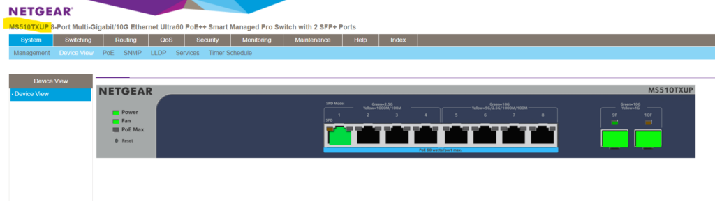
For this post to demonstrate the use of VLANs , I will use a NETGEAR MS510TXUP 8-Port Multi-Gigabit/10G Ethernet Smart Managed Pro Switch resp. two of them connected through a fibre optic connection by using a SFP 10Gigabit Transceiver on each switch connected by a Digitus DK-2533-01-4 – Fibre Optic Cable ( Multimode Fibre MMF ).
SFP+ 10Gb/s, 10GBase-SR, MMF, 850nm 300M The AXS85-192-M3 850nm VCESL 10Gigabit Transceiver is designed to transmit and receive serial optical data links up from8.5 Gb/s to 10.51875 data rate over multimode fiber. (compatible with both 62.5um and 50um LC cables ; supports OM1/OM2/OM3/OM4 fiber cables) https://www.10gtek.com/products/SFP+-10Gb-s-10GBase-SR-MMF-850nm-300M-1.html
Switch 1 connected through a fibre optic connection on port 9 with Switch 2 (also on port 9 ) which is configured as trunk port to forward data for all configured VLANs (trunk port is a member of all these VLANs ) on each switch .
PVID (Port VLAN ID) vs. VLAN Membership
Configure the pvid (default native vlan) the port is associated to, inter-vlan routing on multiple interconnected netgear switches, wildcard mask, using ip acls to filter layer 3 traffic flow, cli modes and common commands, introduction.
A VLAN (Virtual Local Area Network) is a method of logically segmenting a physical network into multiple, isolated networks . Instead of relying solely on physical connections or separate network hardware (e.g. dedicated switches for each single network segment/subnet ) to create distinct networks, VLANs enable network administrators to define and manage multiple broadcast domains within a single physical network .
By default most managed switches will have pre-configured all of its ports with the default VLAN ID 1 , so all ports on the switch are in the same broadcast domain . Therefore all connected devices are able to communicate to each other out of the box (at data link layer Layer 2 of the OSI model) without the need to first configure the switch .
A VLAN (Virtual Local Area Network) ID is a numerical identifier assigned to a VLAN to distinguish it from other VLANs in a network.
A broadcast domain is a single network segment where all devices within that domain can directly communicate with each other at the data link layer (Layer 2 of the OSI model) using broadcast messages .
Broadcast messages are data packets sent out to all ports ( connected devices to that ports) within that single network segment . Devices in the same broadcast domain can therefore efficiently exchange broadcast messages , but these messages do not typically traverse beyond the boundaries of the broadcast domain .
Routers are used to separate broadcast domains , limiting the scope of broadcast traffic and improving network efficiency by reducing unnecessary communication between devices that don’t need to hear the broadcast messages .
Access Ports (Untagged VLAN) vs. Trunk Ports (Tagged VLAN) on Switches
Access ports are used to connect end devices to a specific VLAN mostly used on edge switches (more about edge switches further down), carrying traffic for only that VLAN , while trunk ports are used to interconnect switches , allowing the passage of traffic for multiple VLANs by using VLAN tagging . The specific configuration for access and trunk ports can vary between all the different switch manufacturers .
Access ports can carry traffic for only one VLAN and are unaware of VLAN tags . Any incoming or outgoing traffic on an access port is associated with the VLAN to which the port is assigned (aka PVID see next section).
Trunk ports can carry traffic for multiple VLANs simultaneously . To distinguish between VLANs , trunk ports use VLAN tagging , where each Ethernet frame includes a VLAN tag indicating its VLAN membership .
Trunk ports also known as tagged (T) ports and access ports as untagged (U) ports .
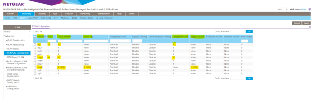
Each trunk port will also have a default native VLAN which is the configured PVID on that port like shown below for the NETGEAR managed switch . The PVID is used for untagged VLANs and you can just associate max one untagged VLAN per trunk port .
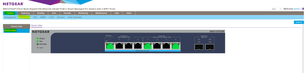
Below for example port 1 and port 5 on the switch are configured as usual access ports (untagged ports) which connects external devices and port 8 as trunk port which can forward traffic for the VLANs 1, 10 and 30 if connected to a different physical switch (interconnect or cascading switches), its default native VLAN is still 1 .
The PVID is the VLAN ID assigned to untagged frames received on a switch port . When a switch port receives untagged frames (frames without VLAN tags) , the PVID determines the VLAN to which those frames are associated .
The PVID represents the native default VLAN the frames will belong to.
Untagged frames are common in scenarios where devices connected to the port are not VLAN-aware . So for example when a switch port is connected to end devices ( such as computers, printers, or IP phones) , that are not VLAN-aware and do not tag their frames with VLAN information , the configured PVID on that port ensures that untagged frames are assigned to the correct VLAN .
When a switch port has a specific PVID configured, it means that any untagged frames arriving on that port will be associated with the specified VLAN . However, these frames themselves remain untagged . The VLAN information is applied at the port level without adding an explicit VLAN tag to the frames . The switch internally processes these untagged frames as part of the specified VLAN , allowing seamless integration of non-VLAN-aware devices into a VLAN-configured network . Access ports (untagged ports) don’t tag frames at all, much more frames are not tagged in general internally on a switch . Internally the switch just uses untagged frames . VLAN tags are only used and added to frames which traverses a trunk port in order to get send out to a neighbor switch . These frames must be tagged in order to retain the VLAN information between different switches .
A VLAN membership in contrast refers to the VLAN to which a particular switch port belongs or is assigned to. A device connected to that port must become a member of a VLAN before it can share the broadcast domain with other devices on that VLAN . For untagged access ports this membership is achieved by the assigned PVIDs to as mentioned previously which is the native default VLAN the port belongs to and is member of.
A port can belong to and be a member of multiple VLANs , just in case it is configured as a trunk port and therefore be able to tag the frames to which each of them belongs to. Trunk ports are designed to transmit data for multiple VLANs between switches and routers .
In the figure below we will see that port 8 has tagged VLANs and therefore is a trunk port which is member in the VLANs 1, 10 and 30 and its default native VLAN (PVID) is VLAN 1 .
Configure VLANs on a NETGEAR managed switch
Below we will see how we can configure a new VLAN on the NETGEAR MS510TXUP 8-Port Multi-Gigabit/10G Ethernet Smart Managed Pro Switch .
Creating a new VLAN
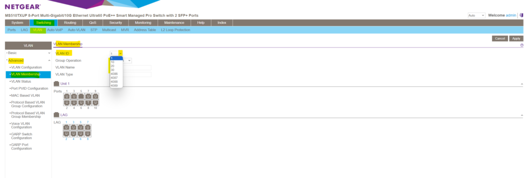
In order to create a new VLAN on this NETGEAR switch we need to navigate to Switching -> VLAN -> Advanced -> VLAN Configuration .
Here by default a new blank top row will appear where we can enter into the VLAN ID field a new ID and besides a new name/description for the VLAN .
The range for VLAN IDs are from 1 to 4095 whereas VLAN 0 and VLAN 4095 are reserved for special purposes. VLAN 0 is used for priority-tagged frames (802.1p) VLAN 4095 is often used to represent untagged frames on a trunk port (for some switch vendors) The maximum value of 4096 for VLANs is derived from the structure of the VLAN header in Ethernet frames . The VLAN ID (VID) field in the VLAN header is a 12-bit field . The 12-bit field allows for 2^12 (4096) unique values. The values range from 0 to 4095 , providing a total of 4096 possible VLAN IDs .
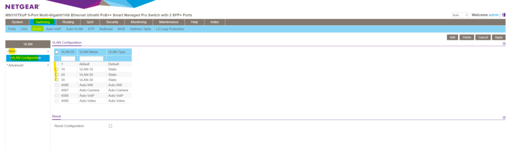
I will user here for the new VLAN the ID 10 , finally click on Add on the right top. Later I will also add two more VLANs with the ID 20 and 30 .
You can use a numbering scheme to allocate VLAN IDs in order to easily identify the purpose of each VLAN . For example you can use the 3rd octet from a subnet you will assign to a VLAN as VLAN ID like shown below. 10.0. 10 .0/24 -> VLAN ID 10 10.0. 20 .0/24 -> VLAN ID 20 10.0. 30 .0/24 -> VLAN ID 30
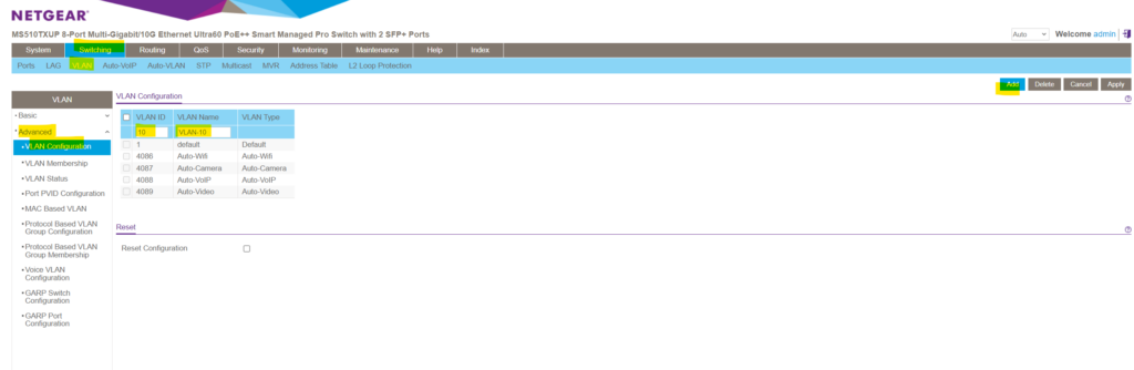
As you can see in the figure above, for managed NETGEAR switches there are by default also further VLANs pre-configured which can’t be used to create a new one.
Default ( VLAN ID = 1 ): Always present Auto-WiFi ( VLAN ID = 4086 ): Always present Auto-Camera ( VLAN ID = 4087 ): Always present Auto-VoIP ( VLAN ID = 4088 ): Always present Auto-VIdeo ( VLAN ID = 4089 ): Always present Static : A VLAN that you configured Dynamic : A VLAN that is created through GVRP registration , that you did not convert to a static VLAN , and that GVRP can therefore remove.
Finally my VLAN configuration will looks like this.
Switching -> VLAN -> Advanced -> VLAN Configuration .
Configure VLAN membership
As already mentioned, by default all ports on the switch are configured as access ports (untagged) and assigned to the default native VLAN ID 1 (PVID) .
So by default all ports on the switch are already a member of VLAN 1 and connected devices to all these ports therefore can communicate on data link layer Layer 2 without any further VLAN configuration on the switch .
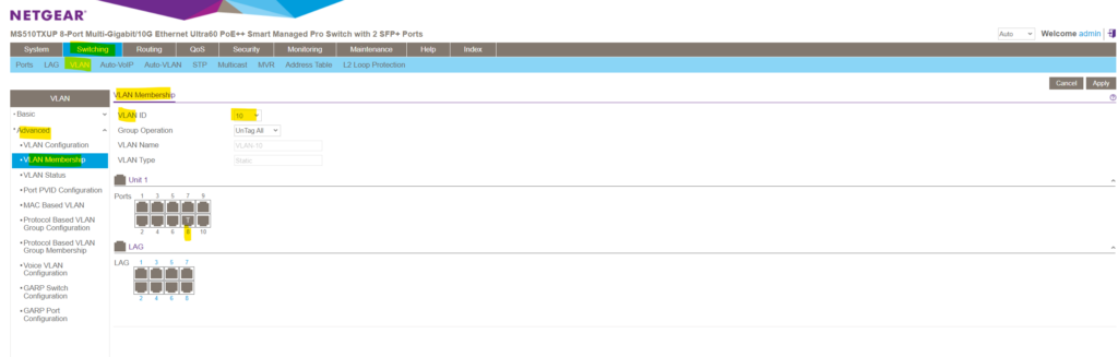
To configure the VLAN membership for a given port, navigate to the following page on the Device UI .
Switching -> VLAN -> Advanced -> VLAN Membership
Here we can select either a predefined VLAN or one of our previously new added VLANs within the VLAN Configuration menu. As mentioned, I was adding the VLANs 10, 20 and 30 for testing and demonstration purpose.
Below for example I will select VLAN 10 . As you can see port 8 is already member of this VLAN and also tagged . This port and its associated VLANs (membership) are tagged in order to forward traffic for the VLANs 1, 10 , 20 and 30 if connected to a different physical switch , its default native VLAN is still 1 .
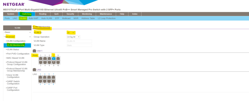
If we now for example also want to add port 7 to be a member of VLAN 10 in order to configure this port also as a trunk , I need to click on this port till it appears as (T) for tagged port and finally need to click on Apply on the right top.
Note! You can here also configure the membership in multiple VLANs for (U) untagged ports which you should avoid. For all untagged ports that are member of a VLAN , tags are removed from all egress packets and will just be forwarded to the VLAN configured as default native VLAN (PVID) on that untagged ports .
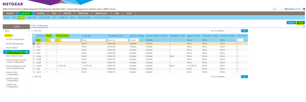
When navigating to Switching -> VLAN -> Advanced -> Port PVID Configuration you will see a summary of all ports and its status . You can also change here the PVID (default native VLAN) , the VLAN membership and if its tagged ( tag name ) or not ( None ) conveniently.
So here below port 8 is tagged and is member in multiple VLANs . So this port is a trunk port which can be used to interconnect with neighbor switches or routers to forward traffic for different VLANs . Connect a neighbor switch on the trunk port in order to forward frames ( data link layer Layer 2 ) between the same configured VLANs on different physical switches or connect a router on the trunk port in order to forward packets ( network layer 3 ) between different configured VLANs on the same or between different switches .
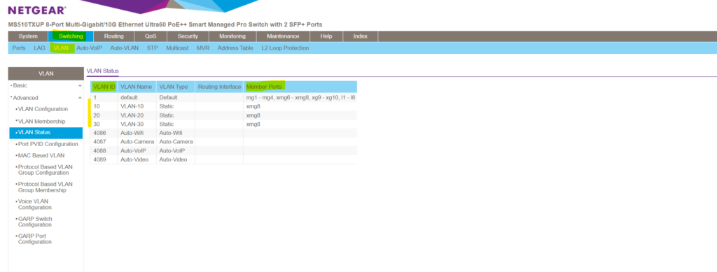
Another summary you will see under Switching -> VLAN -> Advanced -> VLAN Status
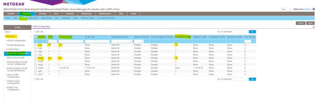
If we now want to connect a new device to a port which should be in a specific different default VLAN , we can change this default PVID on the switch by using the Port PVID Configuration menu .
Navigate to Switching -> VLAN -> Advanced -> Port PVID Configuration and select the port you want to change the PVID .
Change the PVID to the new one and also change the VLAN membership , finally click on the right top on Apply . After applying here my port 1 will be associated to the new VLAN 10 . From that moment on devices connected to port 1 won’t be able to communicate anymore on data link layer Layer 2 with devices connected to port 2-10 and associated with the different default native VLAN 1 . (Except port 8 which is configured as trunk and already member within the VLAN 10 ).
Communication between those devices from now on needs to be established by using network layer 3 routing , either by using a dedicated router or inter-VLAN routing on layer-3-switches as shown further down.
Inter-VLAN routing on the NETGEAR MS510TXUP Switch
In a nutshell, inter-VLAN routing refers to the process of allowing communication between different VLANs within a network. This routing is typically performed by a router or a layer 3 switch , allowing devices on different VLANs to communicate with each other while still maintaining segmentation and security within the network .
Because this NETGEAR managed switch is a layer3 switch , we can enable routing between all configured VLANs on this switch ( inter-VLAN routing ) without using any additional routers just out-of-the-box directly on the layer3 switch .
For layer 2 switches they have configured VLANs , you have to use routers either with multiple interfaces where each interface of the router is connected to ports on the switch configured for the different VLANs or with just one interface (so called router-on-a-stick or one-armed router ) to enable VLAN routing , just as if multiple LANs were physically isolated . Drawbacks are additional costs and effort to deploy a dedicated router , further for each VLAN you want to route you will have to provide a dedicated port which can’t be used anymore for other devices, in case of router-on-a-stick at least one port is additionally used. Generally a layer 3 switch will have much better performance and less latency than a dedicated router because routing is processed directly on the hardware instead of software when using a router .
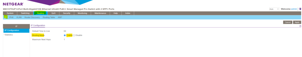
To enable inter-VLAN routing between different VLANs on this NETGEAR managed switch , we first we need to enable in general IP routing on this switch as shown below.
Routing -> IP -> IP Configuration -> Routing Mode -> Enable
The next step for each VLAN on this switch we want to enable inter-VLAN routing for, is to create a dedicated virtual port (so called VLAN routing interface on NETGEAR switches) for each of these VLANs .
On NETGEAR switches, VLAN routing interfaces are often configured by using sub-interfaces . Each sub-interface is associated with a specific VLAN and has its own IP address . This allows the switch to route traffic between VLANs based on the configured sub-interfaces . Sub-interfaces are provided and used for a variety of purposes by several switch and router manufactures. In case of our switch , each sub-interface you will create is associated with one dedicated VLAN and has its own IP address . A sub-interface uses the parent physical ports for sending and receiving data. Sub-interfaces will also be used by routers , they just have one physical interface but needs to route traffic between two different networks like for example as mentioned previously when using a router-on-a-stick aka one-armed router for inter-VLAN routing on layer 2 switches .
As shown I have already created three different VLANs ( 10 , 20 and 30 ) on the switch, now I have also configured two ports where I changed the pre-configured default VLAN ID 1 .
For port 1 I changed the default VLAN ID 1 into 10 and for port 5 into 30 as shown below.
On both ports the following devices (notebooks) are connected to.
Configuration of the devices as follows: Port 1 (VLAN 10 ) -> IP 10.0. 10 .10 Subnet 10.0. 10 .0/24 Port 5 (VLAN 30 ) -> IP 10.0. 30 .10 Subnet 10.0. 30 .0/24 So far neither a default gateway nor a static route is configured on the devices.
On port 8 btw. my notebook from which I will configure the switch is connected to.
As mentioned for each VLAN we want to enable inter-VLAN-routing we need to create a dedicated virtual port (so called VLAN routing interface on NETGEAR switches or in general a so called sub-interface ).
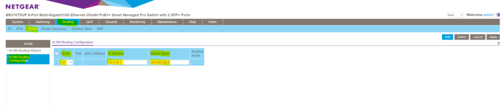
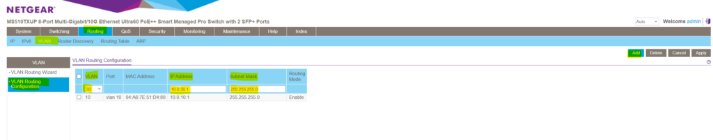
Therefore navigate to Routing -> VLAN -> VLAN Configuration and select the VLAN you want to enable for inter-VLAN-routing .
To create this VLAN routing interface we need to assign an IP address which will act as next hop for the devices within this VLAN to route traffic into different VLANs where also a dedicated VLAN routing interface is configured for.
My subnet within the VLAN 10 is 10.0. 10 .0/24, for this next hop interface I will use therefore the so far not assigned and available IP address 10.0. 10 . 1 .
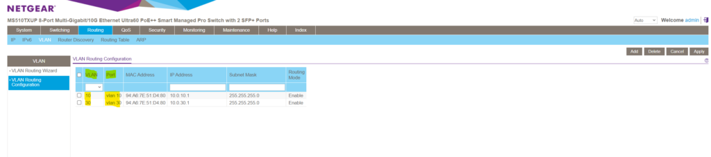
Next I will configure the same for the VLAN 30 where the second device is connected to and I want to enable routing between both. The steps here I think are self-explaining and like previously for VLAN 10 .
In the port column we will see the display name of our newly created VLAN routing interfaces ( sub-interfaces ) for both VLANs we enabled inter-VLAN-routing .
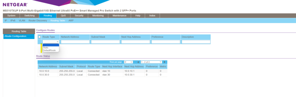
When creating these VLAN routing interfaces ( sub-interfaces ), by default a new route will be added to the routing table on the switch .
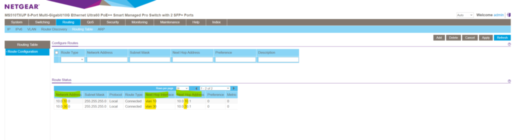
You can also manually add a default or static route to this table.
The default route will be used to route any traffic for which no other route is available for a given IP destination address .
From now on the inter-VLAN-routing configuration on the switch itself is finished, but in order both devices located on those different VLANs can communicate to each other directly, one last final step is needed to be configured on both devices.
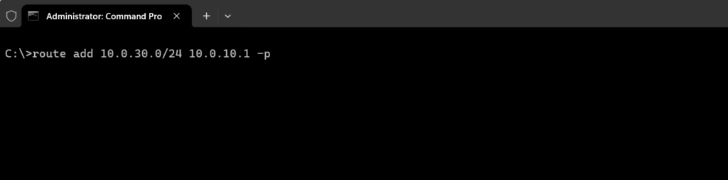
On devices connected to VLAN 10 we need to add a static route for the destination VLAN 30 and vice versa. The next hop is always the created VLAN routing interface ( sub-interface ) resp. its IP address for the VLAN the device itself is connected to. Finally the same as you would use dedicated routers .
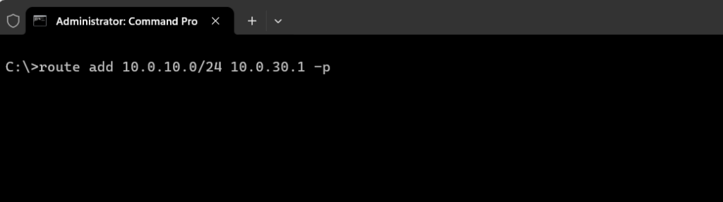
Below I will add a permanet static route for the subnet 10.0. 10 .0/24 on the device which is connected to VLAN 30 .
For the device connected to VLAN 10 I need to add a static route for the subnet 10.0. 30 .0/24.
From now on both devices should be able to communicate with each other and traffic should be routed on layer 3 between both VLANs .
In case we want configure/provision multiple VLANs on multiple NETGEAR switches and also want to enable inter-vlan routing between all those VLANs (e.g. VLAN 10 on switch 1 should be able to send data to VLAN 30 on switch 2 ), we just need to configure an additional trunk port on each switch and add this port as member to all routed VLANs , finally we need to connect both switches by using those trunk ports .
For those trunk ports you will usually use dedicated SFP (Small Form-factor Pluggable ) Ports on each switch to connect to each other by using a fibre optic connection for high performance and less latency as mentioned to the beginning of this post. AXS85-192-M3 850nm VCESL 10Gigabit Transceiver Fibre Optic Cable Digitus ( Multimode Fibre MMF ).
The routing itself we configured previously on just one of both switches , will also work when connecting another NETGEAR switch to by using this trunk port configuration . The VLAN routing interfaces ( sub-interfaces ) just needs to be configured on one of those interconnected switches .
Filter Traffic on NETGEAR Switches
You can use ACLs to control which hosts can access different parts of a network or to decide which types of traffic are forwarded or blocked on an interface/port .
The direction for packet filtering here on a NETGEAR switch is always inbound (ingress) . Therefore you will associate/bind an ACL always directly to the source (port or VLAN) of the traffic to prevent unwanted traffic from traversing your environment.
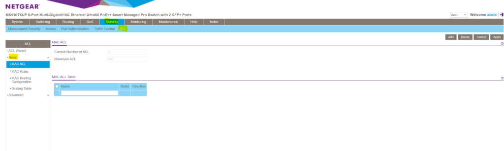
In order to filter traffic based on IPv4 or IPv6 addresses you need to use the Advanced configuration section below, within the Basic section you can just create ACLs based on layer 2 MAC addresses .
Within the Advanced configuration section you can also configure layer 3 IP ACLs .
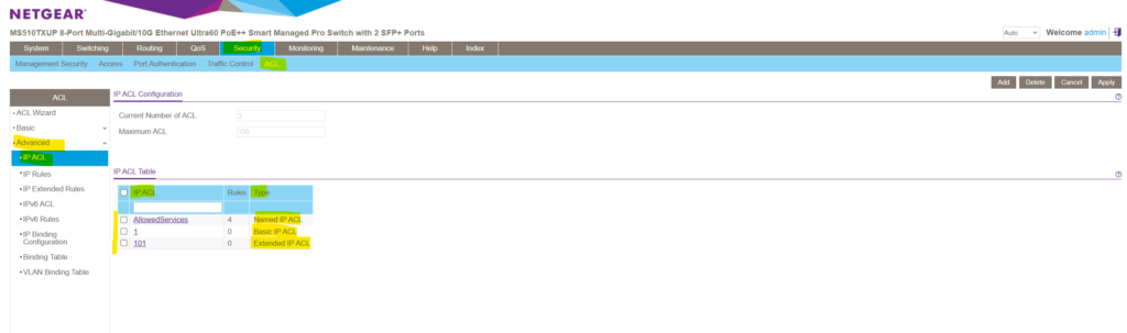
Further there basic or extended IPv4 ACLs . The differences between a basic IPv4 ACL and an extended IPv4 ACL are as follows:
- Numbered ACL from 1 to 99 : Creates a basic IPv4 ACL , which allows you to permit or deny traffic from a source IP address .
- Numbered ACL from 100 to 199 : Creates an extended IPv4 ACL , which allows you to permit or deny specific types of Layer 3 or Layer 4 traffic from a source IP address to a destination IP address . This type of ACL provides more granularity and filtering capabilities than the basic IP ACL .
- Named IP ACL : Creates also an extended IPv4 ACL with a name string that is up to 31 alphanumeric characters in length. The name must start with an alphabetic character.
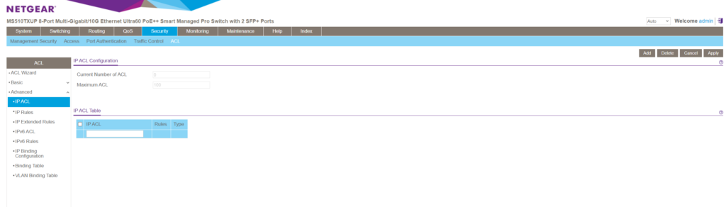
You can create these IPv4 ACLs under Security -> ACL -> Advanced -> IP ACL and enter in the blank top row either a numbered or named ACL as described above.
As explained in the next section, an ACL is a ordered list of classification rules and actions .
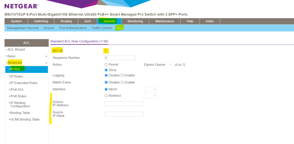
For a basic IPv4 ACL the rule configuration will looks like below. As mentioned, basic IPv4 ACL will allows you to permit or deny traffic just based on the source IP address with no option to filter more granular also for TCP / UDP ports on layer 4 .
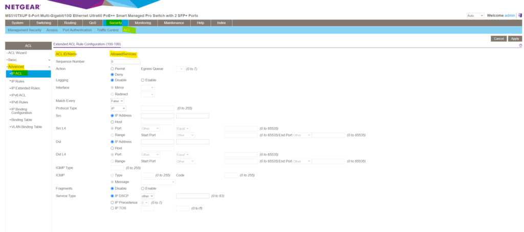
For an extended IPv4 ACL the rule configuration will looks like below. As you can see and mentioned, this type of ACL provides more granularity and filtering capabilities than the basic IP ACL .
ACL vs. ACE
The Access Control List (ACL) feature is part of the device security mechanism. ACLs enable network managers to define patterns ( actions and rules ) for ingress traffic . Packets entering the device on a port with an active ACL , are either admitted or denied entry . If they are denied entry, the port can be disabled.
An ACL is a ordered list of classification rules and actions . Each single classification rule , together with its action , is called an Access Control Element (ACE) . An ACL must have at least one ACE . Each ACE is made up of filters that determine traffic classifications and associated actions. A single ACL may contain one or more ACE , which is matched against the content of incoming frames . Either a DROP or FORWARD action is applied to frames whose content matches the pattern .
The order of the ACEs within the ACL is significant, since they are applied in a first-fit manner . The ACEs are processed in a sequential manner , starting with the first ACE . When a packet matches an ACE classification, the ACE’s action is taken and then that ACL’s processing is stopped. If the packet does not match, the next ACE is processed. If all ACEs of an ACL have been processed without finding a match and if another ACL exists, it is processed in a similar manner ( ACLs are not ordered in a way).
Note ! If no match is found to any ACE in all relevant ACLs , the packet is dropped (as a default action) . The default drop action requires explicitly enabling all permitted traffic , including management traffic, such as telnet, HTTP or SNMP that is directed to the router itself.
Source: https://www.cisco.com/assets/sol/sb/Switches_Emulators_v2_2_015/help/nk_configuring_quality_service03.html
A wildcard mask is similar to a subnet mask but the reverse .
An IPv4 ACE uses a 32-bit wildcard mask to determine which bits of the address to examine for a match. Wildcard masks are also used by the Open Shortest Path First (OSPF) routing protocol.
A wildcard mask is similar to a subnet mask in that it uses the ANDing process to identify which bits in an IPv4 address to match. However, a wildcard mask and a subnet mask differ in the way they match binary 1s and 0s . Unlike with a subnet mask , in which binary 1 is equal to a match , and binary 0 is not a match , with a wildcard mask , the reverse is true.
Wildcard masks use the following rules to match binary 1s and 0s :
- Wildcard mask bit 0: Match the corresponding bit value in the address.
- Wildcard mask bit 1: Ignore the corresponding bit value in the address.
Source: https://www.ciscopress.com/articles/article.asp?p=3089353&seqNum=5
For example, if you have an IP address of 192.168.1.0 and a wildcard mask of 0.0.0.255 , it means that any IP address where the first three octets are the same as 192.168.1 will match the rule , regardless of the value in the fourth octet .
Here’s a quick breakdown:
- IP Address: 192.168.1.0
- Wildcard Mask: 0.0.0.255
This allows any value in the last octet (0-255) to match, making it a wildcard . So, 192.168.1.1 , 192.168.1.2 , …, 192.168.1.255 would match this rule .
Another example are host wildcard masks , when you want to specify a single host rather than a range of IP addresses. A host wildcard mask is essentially a more specific form of a wildcard mask , indicating that only a particular IP address should match.
For example, consider the following:
- IP Address: 192.168.1.5
- Host Wildcard Mask: 0.0.0.0
In this case, the host wildcard mask is set to all zeros ( 0.0.0.0 ), which means that only the exact IP address 192.168.1.5 will match the rule . This is because each bit in the mask is set to 0 , indicating an exact match for the corresponding bit in the IP address .
So, with a host wildcard mask of 0.0.0.0 , only the IP address 192.168.1.5 will match, and no other IP address in the 192.168.1.x range would satisfy the condition.
Using ACLs to control Traffic Flow
Access control lists (ACLs) ensure that only authorized users can access specific resources while blocking any unwarranted attempts to reach network resources. ACLs are used to provide traffic flow control , restrict contents , decide which types of traffic are forwarded or blocked , and provide security for the network .
The NETGEAR managed switch supports a total of 100 ACLs , which can be a combination of MAC ACLs , basic IPv4 ACL , extended IPv4 ACLs , and IPv6 ACLs .
Source: https://www.downloads.netgear.com/files/GDC/MS510TXM/MS510TXM_MS510TXUP_UM_EN.pdf
About how to configure these ACLs in detail on the NETGEAR managed switch you can use the PDF above or under the following page , further down I will just show one simple example to filter traffic by using IP ACLs to filter layer 3 traffic .
IP ACLs classifies layer 3 traffic. Each ACL is a set of up to 10 rules applied to inbound traffic .
Therefore when traffic will flow inbound (ingress) from a source like e.g. a connected end user device to the switch (and associcated VLAN to a specific port ), it will get filtered and dropped directly at the port before it enters the VLAN and therefore will not get forwarded and processed within the switch internally and its backplane as usually for traffic that is allowed to enter the VLAN .
Each rule specifies whether the contents of a given field should be used to permit or deny access to the network , and can apply to one or more of the following fields within a packet:
- Source IP address
- Destination IP address
- Source Layer 4 port
- Destination Layer 4 port
- Protocol number
Note that the order of the rules is important : When a packet matches multiple rules , the first rule takes precedence . Each ACL further has an implicit ( not shown in the rules list ) deny all rule by default at the end of an ACL rule list . That is, if an ACL is applied to a packet and none of the explicit rules match , then the final implicit deny all rule takes effect and the packet is dropped .
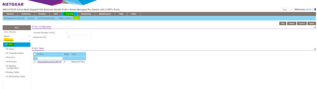
Security -> ACL -> Advanced -> IP ACL
Enter a name for the new IP ACL and click on Add on the right top. Here for example I will create a new ACL which I will associate later to VLAN 30 in order to restrict traffic allowed for this VLAN . Alternatively you can also associate ACLs just to separate ports instead to a complete VLAN .
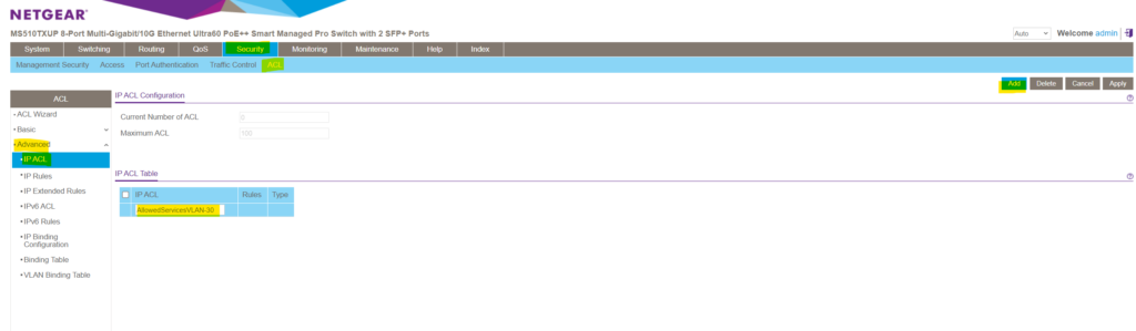
The new IP ACL is added but so far doesn’t include any deny or permit IP Rules .
We can add some extended IP Rules within the Security -> ACL -> Advanced -> IP Extended Rules menu.
Here click on Add .
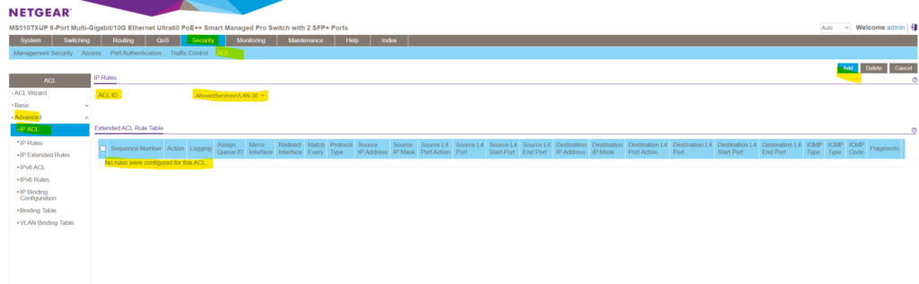
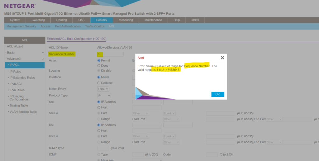
First of all in order to add a new IP Extended Rule you must assign a new valid Sequence Number in the range of 1 to 2147483647 .
And remember! The order of the ACEs within the ACL is significant, since they are applied in a first-fit manner . The ACEs are processed in a sequential manner , starting with the first ACE . When a packet matches an ACE classification, the ACE’s action is taken and then that ACL’s processing is stopped. If the packet does not match, the next ACE is processed. If no match is found to any ACE in all relevant ACLs , the packet is dropped (as a default action) . The default drop action requires explicitly enabling all permitted traffic , including management traffic, such as telnet, HTTP or SNMP that is directed to the router itself.
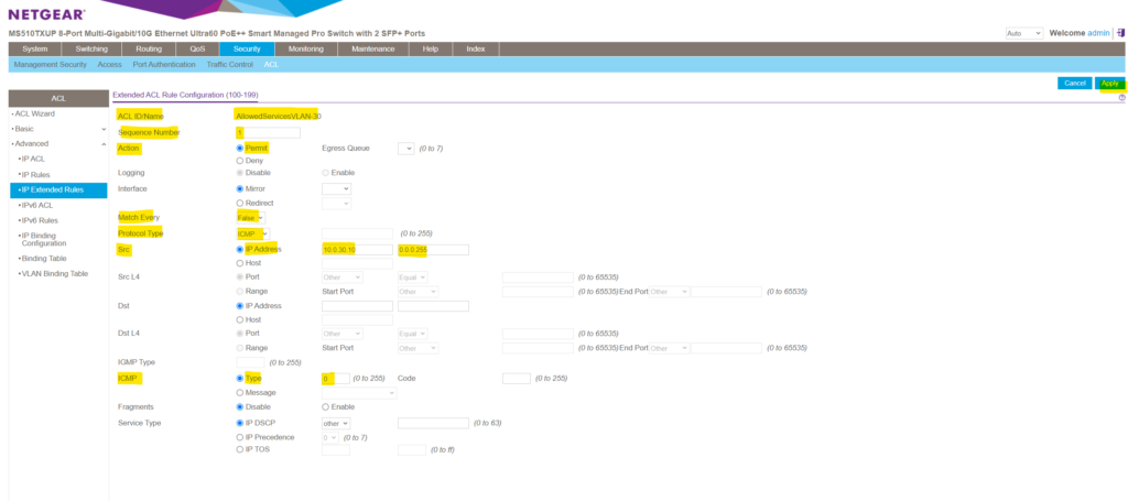
For the first rule aka Access Control Element (ACE) , I will allow ICMP Echo Request and Reply messages ( aka Pings) .
Each single classification rule , together with its action , is called an Access Control Element (ACE)
Here I will first enter a new seqence number starting with 1. Then under Action I choose to permit traffic for this rule. Under match every I will leave by default False , otherwise all packets must match the rule and other rules are not considered.
For the protocol type I will need to select ICMP . Then I want to apply this rule to traffic originated by the VLAN 30 which is associated to the subnet 10.0. 30 .0/24. To match traffic for a /24 subnet we need to enter here the wildcard mask 0.0.0.255 as mentioned further above.
Finally I don’t want to allow all ICMP traffic , just ICMP Echo Request and Reply messages ( aka Pings) . First select Type under ICMP and then for ICMP Echo Request I need to enter the type 8 and for reply type 0 .
ICMP Type Numbers https://www.iana.org/assignments/icmp-parameters/icmp-parameters.xhtml
Finally we add the rule by clicking on Apply .
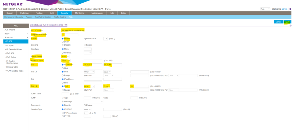
Next I will add three more rules to also allow ICMP Echo Request messages which had type 8 and layer 4 TCP/IP traffic for the HTTP port 80 and HTTPS port 443 protocol.
Here I will add the TCP HTTP port 80 permit rule .
Finally the ACL and all its ACEs (rules) will looks like this.
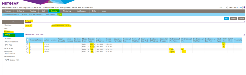
So far we just created all the rules which traffic is permitted to enter a VLAN and what traffic is denied and will be dropped. As mentioned I want to use these rules to filter traffic on VLAN 30 and therefore for my subnet 10.0. 30 .10/24.
To finally apply these rules and therefore will be enabled and active for VLAN 30 , we can either associate the ACL on just dedicated ports for specific devices connected to VLAN 30 or we can associate the ACL directly to a VLAN and therefore by default to all ports which are member of the associated VLAN .
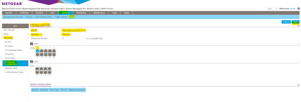
To just associate an ACL with a specific port on the switch , you can navigate to Security -> ACL -> Advanced -> IP Binding Configuration and first select the desired ACL and then associate separate ports by clicking on them as shown below. Finally click on Apply to enable the ACL just for these selected ports .
If you want these rules to be enabled and active on each ports which are member and associated to your affected VLAN , you can also associate the ACL directly to a VLAN as shown below. Therefore navigate to Security -> ACL -> Advanced -> VLAN Binding Table.
In the Sequence Number field, enter an optional sequence number. You can specify an optional sequence number to indicate the order of this access list relative to other access lists that are already assigned to the VLAN ID and selected direction. A lower number indicates a higher precedence order . If a sequence number is already in use for the VLAN ID and selected direction, the specified access list replaces the currently attached ACL using that sequence number. If you do not specify a sequence number (the value is 0) , a sequence number that is one greater than the highest sequence number currently in use for the VLAN ID and selected direction is used.The range is from 1 to 4294967295 .
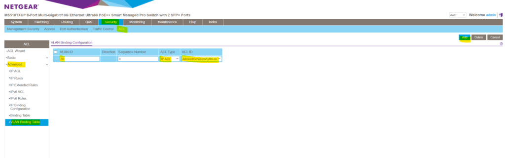
As you can see, by default the lowest available sequence number will be applied to in case you don’t explicitly enter one.
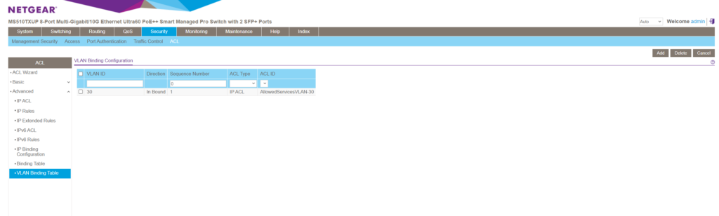
So from now on all devices which are connected to ports on this switch which are associated and member of VLAN 30 , are just able to sent traffic which is permitted by the ACL into VLAN 30 .
Because we didn’t further specify the ACEs (rules) regarding destination subnets, in gerneral just ICMP Echo Request and reply messages and HTTP/HTTPS traffic is allowed to send to the switch and all its VLANs it is a member of by devices connected to VLAN 30 we associated this ACL for.
Manage the NETGEAR MS510TXUP using the Lite CLI
Some NETGEAR Smart Switches now offer a command line interface (CLI) in addition to the local browser user interface (UI) . The NETGEAR Smart Switch CLI does not support all of the configuration options that are available in the local browser UI , so we are calling it a lite CLI .
You can connect to your smart switch’s lite CLI using your preferred Secure Shell (SSH) client .
To access your smart switch’s lite CLI , you must meet the following requirements:
- Your switch model is listed under “This article applies to” on this knowledge article.
- You know the switch’s IP address and administrator password .
- Your switch is running a firmware version that supports the lite CLI
Source: https://kb.netgear.com/000064429/mDGAprccBFuwkbucoaaNIopZdHGsufWx?article=000064429
SSH access is enabled by default under Security -> Access -> SSH -> SSH Configuration . You can also adjust here the SSH Session Timeout .
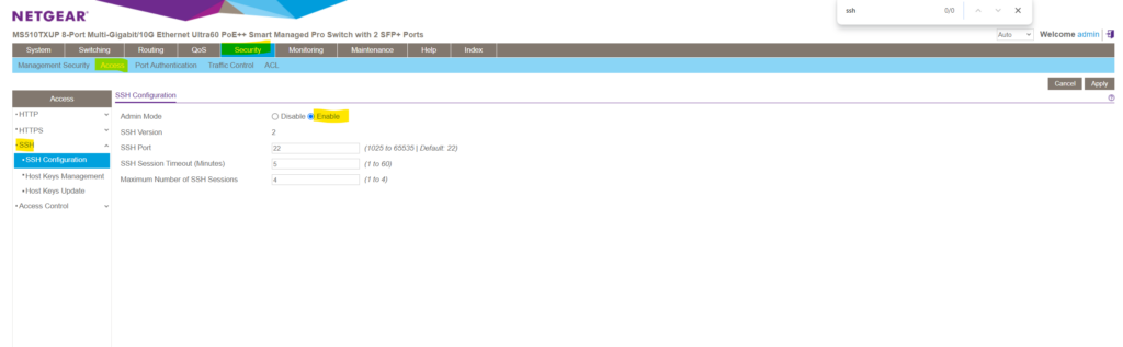
By using PuTTY enter the IP address of your switch and the default SSH Port 22 . For the username I will use below the default admin user and the password I was set for.
Lite CLI Reference Manual https://www.downloads.netgear.com/files/GDC/GS108Tv3/Smart_Switches_CLI_Manual_EN.pdf
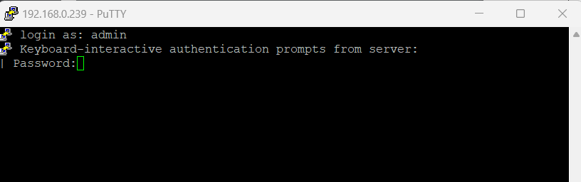
I will get logged on here directly into the privileged EXEC mode which is indicated by the # hashtag prompt as described in the table below.
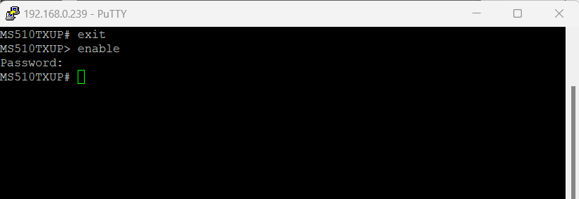
To leave the Privileged EXEC mode in switch to the User Exec mode just enter exit . To return to the Privileged EXEC mode , just enter enable and leave the password blank .
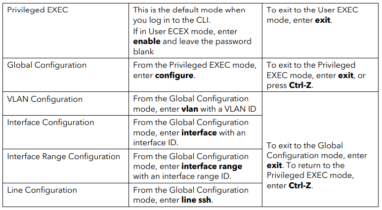
The following table describes how to enter or exit each mode .
Source: https://www.downloads.netgear.com/files/GDC/GS108Tv3/Smart_Switches_CLI_Manual_EN.pdf
The CLI groups commands into modes according to the command function . Each of the command modes supports specific commands . The commands in one mode are not available until you enter that specific mode . The only exception are the User EXEC mode commands , which you execute in either the User EXEC mode or the Privileged EXEC mode .
The command prompt changes in each command mode to help you identify the current mode . The following table describes the command modes and the prompts visible in that mode.
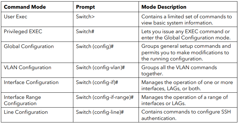
All show commands can be issued from any configuration mode (Global Configuration, Interface Configuration, VLAN Configuration, etc.). The show commands provide information about system and feature-specific configuration, status, and statistics.
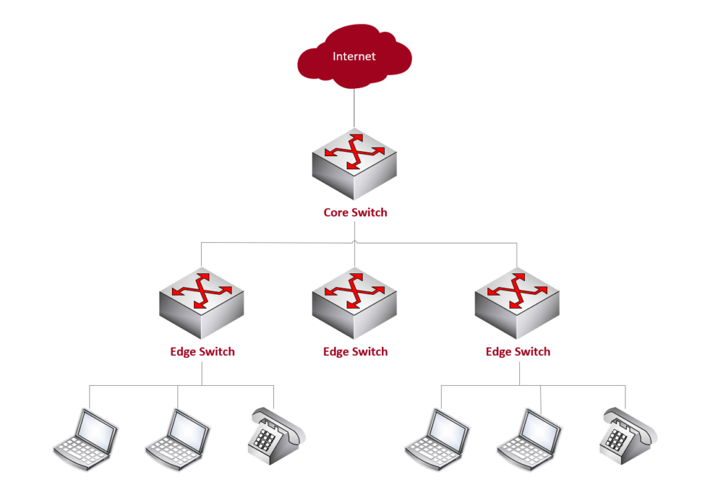
Core Switch vs. Edge Switch
An edge switch is a network switch that operates at the edge of a network . In networking terminology , the edge typically refers to the outermost boundary of a network where it connects to end-user devices or other networks .
Edge switches (aka access node or service node ) play a crucial role in connecting devices such as computers, printers, servers, and other end-user devices to the local area network (LAN) or to other networks .
A core switch is a high-capacity network switch that typically operates at the core (backbone) or center of a computer network . It plays a crucial role in handling the major traffic within the network, connecting various segments of the network together. The core switch is a key component in the hierarchical network architecture commonly used in large enterprise networks.
Reset the switch to factory default settings but maintain the registration status
In case you have locked yourself out and can’t access the switch anymore, you can reset the switch by pressing the Reset button on the front panel for more than 5 seconds but less than 10 seconds . (Do not press the button for more than 10 seconds!)
When pressing the Reset button on the front panel for more than 10 seconds you will reset the switch to factory default settings and reset the registration status .
This option can be useful if you want to register the switch under a different name or account. This option requires you to first contact NETGEAR support at https://netgear.com/support so that the NETGEAR registration status on the NETGEAR server can be reset. Then, you can use this option to erase all settings, reset the switch to factory defaults, go through the initial log-in process again, and reregister the switch with NETGEAR .
How to configure a VLAN on a NETGEAR managed switch https://kb.netgear.com/31026/How-to-configure-a-VLAN-on-a-NETGEAR-managed-switch What are Link Aggregation Groups (LAGs) and how do they work with my managed switch? https://kb.netgear.com/21632/What-are-Link-Aggregation-Groups-LAGs-and-how-do-they-work-with-my-managed-switch What are Access Control Lists (ACLs) and how do they work with my managed switch? https://kb.netgear.com/21708/What-are-Access-Control-Lists-ACLs-and-how-do-they-work-with-my-managed-switch
Related Posts
Remote desktop services (rds) – published rdp icon is gone after publishing further remote apps later, set up and deploy bginfo from sysinternals in your network, zeroconfigexchange & zeroconfigexchangeonce, latest posts, set up and deploy a vmware esxi host cluster and datastore cluster, set up iscsi virtual disks as shared storage for an esxi host cluster, set up a nfs server in windows server 2022, the best home for modern wordpress sites built on the google cloud platform.

IMAGES
VIDEO
COMMENTS
Just like with TCP, UDP uses port numbers to identify the connection between the two applications. The port numbers used with UDP are the same as the ones used with TCP, with well-known ports being assigned numbers between 0 and 1023 and dynamic ports being assigned numbers between 1024 and 65535.
Understanding the purpose and functionality of the Transport Layer (Layer 4 in the OSI model) is fundamental for understanding how data is transmitted in network environments. When preparing for the Cisco CCNA 200-301 exam , you need to have strong knowledge of the Transport Layer of the OSI model and also about TCP/UDP port numbers and their ...
What is the primary purpose of Layer 4 port assignment? to identify devices on the local media. to identify the hops between source and destination. to identify to the intermediary devices the best path through the network. to identify the source and destination end devices that are communicating. to identify the processes or services that are ...
Ports 20 and 21: File Transfer Protocol (FTP). FTP is for transferring files between a client and a server. Port 22: Secure Shell (SSH). SSH is one of many tunneling protocols that create secure network connections. Port 25: Historically, Simple Mail Transfer Protocol (SMTP). SMTP is used for email.
Transport Layer is responsible for Layer-4 Addressing which is also called Process Level Addressing. It allows a computer to use multiple network layer protocols simultaneously. ... The range of Transport Layer Port numbers is from 0-65,535. 65000, because Port number is a 16-bit number & maximum range through which it can span is 65,535.
The OSI model has seven (7) layers. In this article, we will concentrate on Layer 4, which is the Transport Layer. The upper layers, the Application Layer, Presentation Layer, and Session Layer, are responsible for preparing and sending the raw data. In contrast, the lower layers, the Network Layer, Data Link Layer, and Physical Layer, are ...
A data segment is a Service Data Unit, which is used for encapsulation on the fourth layer (transport layer). It consists of protocol elements that contain Layer 4 information control. When addressing the data segment assigned a Layer 4 address, so a port. The data segment is encapsulated in the layer 3 in a data packet.
The Ports are defined in the 5th layer of the OSI model which establishes and controls the dialogue between the source and destination. Port definition is done in the diaogue establishment process. In the TCP/IP model, Layers 5,6 and 7 of the OSI model are included into one Layer (Layer 4 of the TCP/IP model). So to answer your question, it all ...
The combination of the IP address and the port number is called a socket. Learn more about sockets here. Learn more about the differences and similarities between these two protocols here. How to Troubleshoot OSI Layer 4 Problems. Here are some Layer 4 problems to watch out for: All the problems that can crop up on previous layers :)
Port Assigment Description; 20: FTP: File Transfer Protocol (Data) - The File Transfer protocol provides a mechanism for transferring specific files between network connected computer systems (usually a Linux or UNIX based system). Transfer is typically performed using the ftp client which provides a range of commands used to connect to a remote server for the purpose of uploading or ...
This is a list of TCP and UDP port numbers used by protocols for operation of network applications. The Transmission Control Protocol (TCP) and the User Datagram Protocol (UDP) only need one port for duplex, bidirectional traffic.They usually use port numbers that match the services of the corresponding TCP or UDP implementation, if they exist. The Internet Assigned Numbers Authority (IANA) is ...
This chapter focuses on the Transport layer (Layer 4) of the OSI model, which is responsible for transporting the data between the source and destination either via a connection-oriented or a connectionless mechanism. There are various Transport layer protocols that are used to transmit the data, including these:
RFC 7605 Recommendations for Transport Port Use August 2015 registration of port number use. It is the second purpose that drives the need for a common registry. ... Security Considerations This document focuses on the issues arising when designing services that require new port assignments. Section 7.4 ... Eastlake 3rd, D., "Transport Layer ...
One of the many fundamental things to know as a network engineer is the function and port number used by a number of common services as well as many that are typically implemented during the course of a network engineer's career. This article takes a look at these protocols, provides a basic description of their function and lists the port numbers that they are commonly associated with.
Transport Layer (Layer 4) - Reserved TCP and UDP Port Numbers. You must be familiar with these Transport Layer (4) Port assignments. For a complete list -- check out this superb site HERE. Also -- it would be a smart thing to memorize this list: 0 to 254 - used for public applications. 255 to 1023 - assigned to companies* for marketable ...
originate the flow of data. manage data flows. final termination point for data flow. 3. Select the statements that are correct concerning network protocols. (Choose three.) define the structure of layer specific PDU's. dictate how to accomplish layer functions. outline the functions necessary for communications between layers.
The Layer 4 switch, often referred to as a "layer 3 switch with enhancements" or a "layer 3 switch that understands layer 4 protocols," represents an advanced breed of network switch. While traditional switches operate at the data link layer (Layer 2) of the OSI model, the Layer 4 switch extends its purview to the transport layer.
What is the primary purpose of Layer 4 port assignment? to identify the processes or services that are communicating within the end devices. What kind of device is a switch? Intermediary. Which layer encapsulates the segment into packets? Network. What can be identified by examining the network layer header?
What is the primary purpose of Layer 4 port assignment? to identify the processes or services that are communicating within the end devices. What device is considered an intermediary device? switch. Refer to the exhibit. Which term correctly identifies the device type that is included in the area B?
Chapter 2 - Free download as Word Doc (.doc), PDF File (.pdf), Text File (.txt) or read online for free. Based upon the graphic, which device type best describes the function of wireless device? WAN MAN LAN WLAN 4What is a PDU? corruption of a frame during transmission data reassembled at the destination. What is the proper order of the layers of the OSI model from the highest layer to the ...
Layer 4 is transport which encapsulates data as a Segment. This is where port assignments are important. Layer 4 ports are not to be confused with Layer 1 interfaces which are often also called ...
The main aim of this post is to give you a comprehensive guide and introduction about the basics how VLANs, inter-VLAN routing and VLAN Access control lists (ACLs) will work and how you can configure those VLANs on managed layer 3 switches.. For this post to demonstrate the use of VLANs, I will use a NETGEAR MS510TXUP 8-Port Multi-Gigabit/10G Ethernet Smart Managed Pro Switch resp. two of them ...
What is the purpose of the TCP/IP Network Access layer? network media control. What is the proper order of the layers of the OSI model from the highest layer to the lowest layer? application, presentation, session, transport, network, data link, physical. CCNA 1 Chapter 2 Test - Seminole State Learn with flashcards, games, and more — for free.