- Demo Videos
- Interactive Product Tours
- Request Demo

Flowchart Tutorial (with Symbols, Guide and Examples)
A flowchart is simply a graphical representation of steps. It shows steps in sequential order and is widely used in presenting the flow of algorithms, workflow or processes. Typically, a flowchart shows the steps as boxes of various kinds, and their order by connecting them with arrows.

What is a Flowchart?
A flowchart is a graphical representations of steps. It was originated from computer science as a tool for representing algorithms and programming logic but had extended to use in all other kinds of processes. Nowadays, flowcharts play an extremely important role in displaying information and assisting reasoning. They help us visualize complex processes, or make explicit the structure of problems and tasks. A flowchart can also be used to define a process or project to be implemented.
Flowchart Symbols
Different flowchart shapes have different conventional meanings. The meanings of some of the more common shapes are as follows:
The terminator symbol represents the starting or ending point of the system.

A box indicates some particular operation.

This represents a printout, such as a document or a report.

A diamond represents a decision or branching point. Lines coming out from the diamond indicates different possible situations, leading to different sub-processes.

It represents information entering or leaving the system. An input might be an order from a customer. Output can be a product to be delivered.

On-Page Reference
This symbol would contain a letter inside. It indicates that the flow continues on a matching symbol containing the same letter somewhere else on the same page.

Off-Page Reference
This symbol would contain a letter inside. It indicates that the flow continues on a matching symbol containing the same letter somewhere else on a different page.

Delay or Bottleneck
Identifies a delay or a bottleneck.

Lines represent the flow of the sequence and direction of a process.
When to Draw Flowchart?
Using a flowchart has a variety of benefits:
- It helps to clarify complex processes.
- It identifies steps that do not add value to the internal or external customer, including delays; needless storage and transportation; unnecessary work, duplication, and added expense; breakdowns in communication.
- It helps team members gain a shared understanding of the process and use this knowledge to collect data, identify problems, focus discussions, and identify resources.
- It serves as a basis for designing new processes.
Flowchart examples
Here are several flowchart examples. See how you can apply a flowchart practically.
Flowchart Example – Medical Service
This is a hospital flowchart example that shows how clinical cases shall be processed. This flowchart uses decision shapes intensively in representing alternative flows.

Flowchart Example – Simple Algorithms
A flowchart can also be used in visualizing algorithms, regardless of its complexity. Here is an example that shows how flowchart can be used in showing a simple summation process.

Flowchart Example – Calculate Profit and Loss
The flowchart example below shows how profit and loss can be calculated.

Creating a Flowchart in Visual Paradigm
Let’s see how to draw a flowchart in Visual Paradigm. We will use a very simple flowchart example here. You may expand the example when finished this tutorial.
- Select Diagram > New from the main menu.

- Enter the name of the flowchart and click OK .

- Enter Add items to Cart as the name of the process.

Turn every software project into a successful one.
We use cookies to offer you a better experience. By visiting our website, you agree to the use of cookies as described in our Cookie Policy .
© 2024 by Visual Paradigm. All rights reserved.
- Privacy statement

Flowchart Symbols and Notation
What do you want to do with flowcharts.
Don’t be intimidated by the wide array of flowchart shapes. Each symbol has a specific meaning and context where its use is appropriate. If you get confused while drawing your flow chart, remember that most charts can be drawn with just a few common symbols, which are listed below.
4 minute read
Want to create a flowchart of your own? Try Lucidchart. It's fast, easy, and totally free.
Common flowchart symbols
These flowchart shapes and symbols are some of the most common types you'll find in most flowchart diagrams.
Additional flowchart symbols
Many of these additional flowchart symbols are best utilized when mapping out a process flow diagram for apps, user flow, data processing, etc.
Standard vs. non-standard flowchart symbols
Additional resources.
- How to Make a Flowchart in Excel
- What is a flowchart and how to create one
- How to Make a Flowchart
- How to Make a Flowchart in PowerPoint
- How to Make a Flowchart in Word
- What is a Flowchart
If we don’t have the shape you’re looking for, Lucidchart allows you to also upload any and all shapes you want to use in addition to our own extensive shape library. Try mapping out your process flow with Lucidchart today!
- Spider Diagram Guide
- 5 Whys Template
- Assumption Grid Template
- Brainstorming Templates
- Brainwriting Template
- Innovation Techniques
- 50 Business Diagrams
- Business Model Canvas
- Change Control Process
- Change Management Process
- NOISE Analysis
- Profit & Loss Templates
- Scenario Planning
- Winning Brand Strategy
- Work Management Systems
- Developing Action Plans
- How to Write a Memo
- Improve Productivity & Efficiency
- Mastering Task Batching
- Monthly Budget Templates
- Top Down Vs. Bottom Up
- Weekly Schedule Templates
- Kaizen Principles
- Opportunity Mapping
- Strategic-Goals
- Strategy Mapping
- T Chart Guide
- Business Continuity Plan
- Developing Your MVP
- Incident Management
- Needs Assessment Process
- Product Development From Ideation to Launch
- Visualizing Competitive Landscape
- Communication Plan
- Graphic Organizer Creator
- Fault Tree Software
- Bowman's Strategy Clock Template
- Decision Matrix Template
- Communities of Practice
- Goal Setting for 2024
- Meeting Templates
- Meetings Participation
- Microsoft Teams Brainstorming
- Retrospective Guide
- Skip Level Meetings
- Visual Documentation Guide
- Weekly Meetings
- Affinity Diagrams
- Business Plan Presentation
- Post-Mortem Meetings
- Team Building Activities
- WBS Templates
- Online Whiteboard Tool
- Communications Plan Template
- Idea Board Online
- Meeting Minutes Template
- Genograms in Social Work Practice
- How to Conduct a Genogram Interview
- How to Make a Genogram
- Genogram Questions
- Genograms in Client Counseling
- Understanding Ecomaps
- Visual Research Data Analysis Methods
- House of Quality Template
- Customer Problem Statement Template
- Competitive Analysis Template
- Creating Operations Manual
- Knowledge Base
- Folder Structure Diagram
- Online Checklist Maker
- Lean Canvas Template
- Instructional Design Examples
- Genogram Maker
- Work From Home Guide
- Strategic Planning
- Employee Engagement Action Plan
- Huddle Board
- One-on-One Meeting Template
- Story Map Graphic Organizers
- Introduction to Your Workspace
- Managing Workspaces and Folders
- Adding Text
- Collaborative Content Management
- Creating and Editing Tables
- Adding Notes
- Introduction to Diagramming
- Using Shapes
- Using Freehand Tool
- Adding Images to the Canvas
- Accessing the Contextual Toolbar
- Using Connectors
- Working with Tables
- Working with Templates
- Working with Frames
- Using Notes
- Access Controls
- Exporting a Workspace
- Real-Time Collaboration
- Notifications
- Meet Creately VIZ
- Unleashing the Power of Collaborative Brainstorming
- Uncovering the potential of Retros for all teams
- Collaborative Apps in Microsoft Teams
- Hiring a Great Fit for Your Team
- Project Management Made Easy
- Cross-Corporate Information Radiators
- Creately 4.0 - Product Walkthrough
- What's New
Ultimate Flowchart Tutorial | Learn What is a flowchart and How to create a flowchart
So you want to learn flowcharts? Well, This flowchart tutorial will teach you all you need to know. It will cover the history of flowcharts, flowchart symbols, how to create flowcharts, flowchart best practices and we’ve also included a section to answer frequent questions about flowcharts. Best of all you can use our flowchart software.
Creately already has some really awesome articles and videos covering various things related to flowcharts like meanings of flowchart symbols, how to use swimlanes in flowcharts, flowchart best practices, case studies, and much more.
History of Flowcharts
Frank Gilberth introduced flowcharts in 1921, and they were called “Process Flow Charts” at the beginning. Allan H. Mogensen is credited with training business people on how to use flowcharts. Wikipedia has a great summary of the history of flowcharts, read more in this wiki section .
What is a Flowchart
Flowcharts are visual representations of processes and systems, showing the various steps, decision points, and paths through a process. In a wide range of fields, including software development, engineering, business, and education, it is used to help understand, analyze, and optimize processes. A well-designed flowchart should be easy to read and follow a logical sequence of steps.
Flowchart Symbols

Flowchart symbols are graphical representations of various components of a process or system. Each symbol is used to denote a particular action, decision, or result in the process being represented. Each symbol also has a specific meaning.
So what are the different symbols used in a flowchart?. Most people are only aware of basic symbols like processes and decision blocks. But there are many more symbols to make your flowchart more meaningful. The above image shows all the standard flowchart symbols.
The most common symbol used in a flowchart is the rectangle. A rectangle represents a process, operation, or a task. The next most common symbol is the diamond which is used to represent a decision.
With this following list, you can figure out the most commonly used flowchart symbols as well as those that are little-known. All these shapes are available in Creately and you can try out a demo or take a look at some flowchart examples for more context.
Terminal / Terminator

The terminator shows where your process begins or ends. You can use words like ‘Start’, ‘Begin’, ‘End’ inside the terminator shape to make things more obvious.
Process / Rectangle

Flowchart process shape is used to represent a process, action step, or operation. While these are pictured with rectangles, the text in the rectangle mostly includes a verb. For example, ‘Edit Video’, ‘Try Again’, ‘Choose Your Plan’.n’.

The Data object, often referred to as the I/O Shape shows the Inputs to and Outputs from a process. This takes the shape of a parallelogram.
Decision / Conditional

The decision shape is represented as a Diamond. This object is always used in a process flow to ask a question. And, the answer to the question determines the arrows coming out of the Diamond. This shape is quite unique with two arrows coming out of it. One from the bottom point corresponding to Yes or True and one from either the right/left point corresponding to No or False. The arrows should always be labeled to avoid confusion in the process flow.

The document object is a rectangle with a wave-like base. This shape is used to represent a Document or Report in a process flow.
Stored Data

This is a general data storage object used in the process flow as opposed to data that could be also stored on a hard drive, magnetic tape, memory card, of any other storage device.
Direct Data

Direct Data object in a process flow represents information stored which can be accessed directly. This object represents a computer’s hard drive.
Internal Storage

This is a shape that is commonly found in programming flowcharts to illustrate the information stored in memory, as opposed to on a file. This shape is often referred to as the magnetic core memory of early computers, or the random access memory (RAM) as we call it today.
Sequential Access

This object takes the shape of a reel of tape. It represents information stored in a sequence, such as data on a magnetic tape.
Manual Input

This object is represented by a rectangle with the top sloping up from left to right. The Manual Input object signifies an action where the user is prompted for information that must be manually input into a system.
Subroutine / Predefined Process

This shape takes two names – ‘Subroutine’ or ‘Predefined Process’. Its called a subroutine if you use this object in flowcharting a software program. This allows you to write one subroutine and call it as often as you like from anywhere in the code.
The same object is also called a Predefined Process. This means the flowchart for the predefined process has to be already drawn, and you should reference the flowchart for more information.
Although these are the standard symbols available in most flowchart software, some people do use different shapes for different meanings. The most common example of this is using circles to denote start and end. The examples in this flowchart tutorial will stick with the standard symbols.
How to Draw a Flowchart
How do you draw a flowchart? Well, our flowcharting tool is a good place to start. But before directly using the tool, let’s take a look at some basics.
There are four main types of flowcharts. Document flowchart, System flowchart, data flowchart, and program flowchart. Not everyone agrees with this categorization, but the core principles of drawing a flowchart remain the same. You need to consider a few things when drawing a flowchart, Check out 6 useful tips on drawing flowcharts before you start.
If you are drawing a flowchart with many responsible parties you can group them together using swimlanes. Swimlanes are a powerful technique to increase the readability of your flowchart so you should use them according to the situation. Read how to use cross-functional flowchart for planning to learn more about the process.
The below video shows how to draw a flowchart using Creately. It is very simple to use and one-click create and connect helps you draw them faster as well. You can drag and drop symbols from the library or drag images to your diagram by doing an image search.
Here are the Steps to Draw a Flowchart
1. explain the procedure.
Determine the function and boundaries of the system or process you wish to depict in the flowchart. The process’s inputs, outputs, and actions should be identified.
2. Choose the shapes and symbols
To represent the many process components—such as the start and end points, inputs, outputs, actions, decisions, and loops—choose the right symbols and shapes. Rectangles, diamonds, circles, and arrows are the most often utilized shapes in flowcharts. To access all shapes, enable Creately’s flowchart shapes library.
3. Organize the flow
Determine the order of the steps in the process and the different paths that can be taken. This will help you organize the flow of the flowchart. Use Creately’s Plus Create to add the next shape and the connector in a single click.
4. Review and revise
Check that the flowchart accurately depicts the procedure and is simple to read and understand. If required, revise it to make it more precise and understandable. Share feedback using Creately’s contextual comments.
5. Share the flowchart
Distribute the flowchart to coworkers, stakeholders, or clients who will need to use it or refer to it easily with a workspace link
Flowchart Templates and Examples
Although you can start drawing flowcharts by scratch it is much easier to use templates. They help you reduce errors and remind you about the best practices to follow. If you want to use a ready-made template, go to the flowchart examples section and click on the flowchart that best suits you. Click on the use at template after the image and you are ready to draw your flowchart.
Below are two templates out of hundreds of flowchart templates available to the user. Click on any of them to start drawing flowcharts immediately.

- Ready to use
- Fully customizable template
- Get Started in seconds

Flowchart Best Practices
There are a few things you can do to make your flowchart universally accepted. And there are some things that you can do to make it visually pleasing to others as well.
If you’re planning to share your flowchart or hoping to use it on a presentation etc. then it’s wise to use standard symbols. However, it is important to remember that the idea is to give out information in an easy-to-understand manner. It is perfectly acceptable to use an alternative image instead of the document symbol as long as the audience understands it.
Keeping the arrow flow to one side, using the same size symbols, naming the decision blocks, processes, arrows, etc. are a few things you can do to make it better. The common mistakes section covers most of these practices in detail.
Map out any process, workflows, or system with ease. Dedicated shape library, drag and drop interface, and powerful diagramming for super-fast drawing.
Common Mistakes Made when Drawing Flowcharts
This section highlights the common mistakes made when drawing flowcharts. Some of the things mentioned here are to make it better looking and more understandable, not having them in your flowchart won’t make it wrong. Since there are two posts covering these mistakes in-depth I will link to them from this flowchart tutorial.
Effective Use of Flowcharts – Case Studies
A flowchart tutorial isn’t complete without some case studies. Below are three case studies and real-life examples of how flowcharts can help you make decisions.
- Ten Flowchart Ideas for Your Business – How flowcharts can be used in making business decisions and optimizing the current business processes
- Analyzing Sales Funnel with Flowcharts – How to analyze the Google analytic sales funnel using a flowchart.
- Flutterscape Case Study – How one of our customers used flowcharts to enhance their processes.
Frequently Asked Questions About Flowchart
The comments section of this article is full of questions. Please note that I will not draw flowcharts for specific scenarios. Below I have answered some of the most frequently asked questions.
Q 01 : What is a subprocess in a flowchart?
Answer: Sometimes complex processes are broken down into smaller sub-processes for clarity. So a flowchart can point to a different sub-process within its flow. The predefined process symbol is used to show such subprocesses.
Q 02 : How are flowcharts used in computer programming?
Answer: A computer program consists of many processes and flows. Flowcharts are used to visualize the processes and make them understandable for non-technical people. They are also used to visualize algorithms and comprehend pseudo-code which is used in programming.
Comments and Feedback on the Flowchart Tutorial
I hope this flowchart tutorial will help you to come up with awesome flowcharts. Flowcharts are a great way to present complex processes in a simple-to-understand manner and they are used all over the world in many industries. If you have a question about drawing flowcharts or have any suggestions to improve this post, feel free to mention in the comments section.
More Diagram Tutorials
- Sequence Diagram Tutorial: Complete Guide with Examples
- Business Process Modeling Tutorial (BPM Guide Explaining Features)
- Use Case Diagram Tutorial (Guide with Examples)
Join over thousands of organizations that use Creately to brainstorm, plan, analyze, and execute their projects successfully.
More Related Articles

Software engineer turned tech evangelist. I handle marketing stuff here at Creately including writing blog posts and handling social media accounts. In my spare time, I love to read and travel.
We use essential cookies to make Venngage work. By clicking “Accept All Cookies”, you agree to the storing of cookies on your device to enhance site navigation, analyze site usage, and assist in our marketing efforts.
Manage Cookies
Cookies and similar technologies collect certain information about how you’re using our website. Some of them are essential, and without them you wouldn’t be able to use Venngage. But others are optional, and you get to choose whether we use them or not.
Strictly Necessary Cookies
These cookies are always on, as they’re essential for making Venngage work, and making it safe. Without these cookies, services you’ve asked for can’t be provided.
Show cookie providers
- Google Login
Functionality Cookies
These cookies help us provide enhanced functionality and personalisation, and remember your settings. They may be set by us or by third party providers.
Performance Cookies
These cookies help us analyze how many people are using Venngage, where they come from and how they're using it. If you opt out of these cookies, we can’t get feedback to make Venngage better for you and all our users.
- Google Analytics
Targeting Cookies
These cookies are set by our advertising partners to track your activity and show you relevant Venngage ads on other sites as you browse the internet.
- Google Tag Manager
- Infographics
- Daily Infographics
- Graphic Design
- Graphs and Charts
- Data Visualization
- Human Resources
- Training and Development
- Beginner Guides
Blog Graphs and Charts
Flowchart Symbols and Meaning: A Complete Guide (2024)
By Danesh Ramuthi , Feb 29, 2024

Flowchart symbols are used to show the steps, order and choices in a process. Together, they form a universal language that makes process analysis easy.
I’m sure you’ve seen flowcharts before with various shapes, lines and arrows to depict stages within a process like where it begins or ends.
Understanding what these symbols mean enhances communication, facilitates problem-solving and ultimately guides process improvement.
In this post, I’ll review flowchart symbols and their meaning. By the way, when creating a flowchart, I suggest using a Flowchart Maker or editing flowchart templates that let you add, remove, and edit these shapes and symbols.
Click to jump ahead:
- What shapes are most frequently used in a flowchart?
List of flowchart symbols and their meanings
What shapes are most frequently used in a flowchart .
One reason why flowcharts are so popular is because they use standardized shapes that almost anyone can instantly recognize.
Here are the five most common shapes used in a flowchart.
- Oval (Terminal symbol)
- Rectangle (Process symbol)
- Arrow (Arrow Symbol)
- Diamond (Decision symbol)
- Parallelogram (Input/Output symbol)

You can see most of these shapes in the following flowchart examples:

Related: Learn how to create a flowchart .
Every shape found in a flowchart has a use case (it’s not just a design preference!)
In this section, I’ll first name the shape, show it to you, and then describe its function.
1. Oval/Pill (Terminal symbol)

The oval shape, also known as the terminal symbol, is as an elongated circle or an ellipse.
Its function is to provide a visual reference of the start or end of a flowchart.
To make sure readers understand the start and endpoint correctly, you should verbally communicate “Start” and “End”.
2. Rectangle (Process symbol)

A rectangle is used to highlight each specific task or action within a process.
Also known as the process symbol, the rectangle is fundamental to mapping out the sequence of actions or operations that take place from the start to the end of a process.
By placing tasks within a rectangle, flowcharts make it easy to understand, follow, and analyze individual tasks that contribute to the overall workflow.
3. Diamond (Decision symbol)

A diamond or a rhombus highlights a decision point in a flowchart and hence is also known as the decision symbol.
Diamonds are usually present when there is a conditional statement such as a “Yes” or “No” or “True” or “False” question.
As a result, two or more paths always branch out from this symbol.
Here’s a great example:

4. Parallelogram (Input/output symbol)

A parallelogram in flowchart represents both input and output processes within a system.
This means it marks the point in a process where a user has to enter data into a system, such as an online shopper entering their name, address, and payment details, into the system.
But the parallelogram can also also refer to a point when system generates data such as an order confirmation number from the example above.
Therefore, it’s good practice to indicate whether the process is an input or an output using labels or arrows.

An arrow usually connects two rectangles, parallelograms or diamond symbols to highlight a sequence flow between the two.
The sole purpose of arrows is to provide visual direction to your flowchart.
6. On-page connector symbol

The on-page connector symbol in a flowchart is a fancy way of referencing a circle.
This shape connects two or more separate paths within a flowchart without the need for long, intersecting lines that can make the flowchart difficult to follow.
Think of the circle as a connecting bridge.
7. Off-page connector symbol

The off-page connector is a five-pointed polygon.
They’re usually seen complex multi-page flowcharts to indicate that the process continues on a different page.
The off-page connector is typically accompanied by a reference point, such as a page number, section identifier, or a unique code to guide the reader to the exact location where the process continues.
8. Document symbol

The document symbol looks like a rectangle with a wavy line below it.
Its design is intended to resemble a piece of paper which is also a hint of its function to indicate a point in the workflow where documentation is integral to the process.
The document symbol is particularly useful for administrative procedures, quality assurance protocols, or any process where record-keeping and documentation is key.
9. Multiple documents symbol

The multiple documents symbol looks like a stack of papers which again hint to its purpose.
This symbol indicates that a step requires the handling, review, or generation of a collection of documents instead of just one.
It’s particularly useful in representing steps that require compiling of reports or processing of multiple forms.
10. Preparation symbol

The preparation symbol is a six point polygon shape (some also refer to it as a rectangle with pointy bits).
The symbol is used to indicate a step where you need to gather resources or engage in specific tasks to ensure a smooth transition into a workflow.
The preparation symbol alerts users to the fact that certain conditions must be met before they can move forward.
11. Manual operation symbol

The trapezoid, which has a longer top side, is used denote a non-automated process that requires manual intervention or handling.
The trapezoid can help identify where human resources are needed and/or and where bottlenecks can occur due to manual operation.
12. Summoning junction symbol

A circle divided into four slices, known as the summoning junction symbol, references a point in the flowchart where multiple branches converge into a single process.
You’ll see this symbol used in complex workflows where different sequences lead to a common action point.
The junction point can be used to indicate that a common path will follow regardless of the preceding steps before it.
13. Merge symbol

The merge symbol is represented by a triangle and is used to combine two or more lists into a single flow.
The merge symbol is a way to communicate the coming together of multiple inputs or sequences.
The pointed end of the triangle faces the direction of the flow, so it’s a way to visualize where a merge happens and the unified process that follows.
14. Collate symbol

The collate symbol is represented by an hourglass shape and indicates the gathering, arranging, or organizing of items in a specific order or sequence.
This symbol is useful in processes where information needs to be organized before it can be processed or analyzed.
15. Sort symbol

A sort symbol is represented by two isosceles triangles joined together on the longest side.
This symbol is useful in processes where data or items need to be classified and ordered in a way that facilitates further actions or decisions.
For example, it could be used to represent the sorting of customer feedback into categories of priority or the organization of products by type before inventory.
16. Or symbol

The Or symbol looks awfully similar to the summoning junctions symbol but don’t confuse them because they have different use cases.
For reference, the Or symbol is a circle with a “Plus sign” inside it rather than an “X.”
The Or symbol is used to denote a point in the process where a decision is made and the outcome of that decision dictates the next step in the process.
17. Loop limit symbol

The loop limit symbol is represented as a rectangle with squared-off top edges.
The purpose of the loop limit symbol is to show where and when a looping action, which could otherwise continue indefinitely, should stop.
This symbol is commonly seen in flowcharts related to programming workflows.
18. Delay symbol

The delay symbol has the appearance of an elongated semi-circle.
It’s used to mark points where delays or waiting periods are expected within a process
For example, in a manufacturing workflow, this symbol might indicate a cooling period required after a product has been heated.
Adding the length of delay in the symbol (if you know it) makes this symbol more useful.
19. Internal storage symbol

A rectangle with two lines going across its length and width is known as the internal storage symbol.
It’s used mainly in software design flowcharts and represents a specific type of data storage or memory that is internal to the system being described.
20. Data storage or stored data symbol

The stored data symbol appears as a curved piece of paper and is used in programming flowcharts.
It’s used to denote where data is stored outside of the immediate processing environment.
This symbol illustrates the interaction between the process and external data storage facilities, such as databases, file systems, or cloud storage services.
21. Database symbol

The database symbol resembles a stack of cylinders and indicates the involvement of a database in the process.
This symbol in flowcharts showing data-intensive processes, such as querying information, updating records, or performing transactions within a database.
22. Display symbol

The display symbol looks like the delay symbol merged with an isosceles triangle on one side.
This symbol shows where user interaction occurs within a system and is important in processes that require data to be presented to the user.
23. Hard disk symbol

The hard disk symbol is essentially a cylinder lying on its curved side.
This symbol indicates when data is stored on a hard drive. It’s used to show points in a process where data is written to or read from a hard disk.
24. Alternate process symbol

The alternate process symbol looks like a rectangle with rounded corners.
It’s used to denote a step that deviates from the main process and represents an alternative method or pathway for accomplishing a task.
Conclusion: Create flowcharts with all these symbols and more using Venngage
When making a flowchart, the last thing you want to worry about is if the software has all the shapes and symbols you need.
With Venngage, you’ll not only get that but access to our in-editor library of images, shapes, and diverse icons that’ll bring your flowchart to life.
Frequently asked questions (FAQ)
What is a flowchart?
A flowchart is a visual representation that outlines each step or decision point in a process. Think of flowcharts as a roadmap of your workflow.
What is input/output in a flowchart?
Input/output in flowcharts indicate when data enters or leaves a system. For example, in online booking system, a parallelogram labeled “Enter Booking Details” represents the input where customers submit their information and another another parallelogram labelled “Send Email Confirmation” indicates the output where the system sends a confirmation email to the customer.
What are the types of flowcharts?
There are 8 main types of flowcharts . They include: 1) Process flowchart, 2) Decision flowchart, 3) Workflow flowchart, 4) Swimlane flowchart, 5) Use case flowchart, 6) EPC flowchart, 7) System or program flowchart, and 8) Data or document flowchart.
What are the 8 basic symbols of a flowchart?
The eight main symbols used in a flowchart are 1) Rectangle, 2) Diamond, 3) Parallelogram, 4) Triangle, 5) Circle, 6) Trapezoid, 7) Hexagon, 8) Circle.
Are workflow diagrams and flowcharts the same?
Workflow diagram and a flowchart aren’t the same. A workflow diagram is a specific type of flowchart focused on illustrating the sequence of steps and the flow of tasks of particular process while a general flowchart can be used for a wide range of purposes, from programming to decision-making processes. They’re not limited to depicting workflows.
The Ultimate Flowchart Guide 2023
This guide is brought to you by Zen Flowchart , the simplest free flowchart maker.
All you need to know about flowcharts (or flow chart): Definition, History, Flowchart Symbols, Flowchart Examples & Templates, What Flowcharts Are and How To Use Them.
Table of Contents
- Flowchart Definition
- When to Use a Flowchart?
- History of Flowcharts
- Flowchart Symbols & Components
- How to Create a Flowchart
- Types of Flowcharts
- Flowchart Tools
- Flowchart Examples
1. Definition / What is a Flowchart?
In the most basic sense, flowchart or flow chart , is a type of diagram that describe processes.

Flowchart represents information or processes as boxes, lines, and text. The boxes represent activities, the lines (or flowlines ) represent the workflow that connects them, and the text represents what happens at each activity. A flowchart can be drawn by hand on paper or projected on a whiteboard. A flowchart consists of a set of interconnected shapes which signify process steps, decision points (if-then branches), or headings.
Let’s take a quick example:
Let’s say you need to write up the instruction of the first step to clean your home, which would be deciding whether to throw away or keep an item (courtesy of Marie Condo’s cleaning method).
Here would be the text-only instruction, and the very same instruction presented in flowchart form:
INSTRUCTION : Follow the following steps. First, pick up an item, then ask yourself: “Does this item spark joy for me?”. If the answer is Yes, the keep the item. If the answer is No, then discard the item. Then, repeat the process until you have gone through all of your items.

This is only a made-up scenario, and in which case, flowchart is not that helpful because the text-based instruction is already quite easy to follow. But as you can imagine, for processes with numerous steps and complex rules, flowchart can be a powerful tool to describe processes clearly and concisely.
Since its invention, flow chart has expanded its usage to different functions and industries, with various types serving specific purposes. Alternate names for “ flowchart ” may include process flowchart, functional flow chart, process map, process chart, functional process chart, business process model, process model, process flow diagram, work flow diagram, business flow diagram , etc.
2. When to Use a Flowchart?
Flowchart is a very simple yet powerful tool to improve productivity in both our personal and work life. Here are some ways flowchart can be helpful:
- Document a process
- Present solution to a problem
- Brainstorm ideas in a meeting
- Design an operation system
- Explain a decision making process
- Store information
- Draw an organizational chart
- Create a visual user journey
- Create a sitemap
3. History of Flowcharts
It's hard to set the records straight on who was the true inventor of flowcharts, but we do have records of the first standardized documentation on flow chart, which was first introduced by Frank and Lillian Gilbreth.
In 1921, the Frank and Lillian presented what was only a "graphic-based method" in a presentation titled: “Process Charts: First Steps in Finding the One Best Way to do Work”, to members of the American Society of Mechanical Engineers (ASME).
In 1930s, Allan H. Mogensen, an industrial engineer trained some participants in his Work Simplification Conferences in New York. Afterwards, participants from this conference such as Art Spinanger and Ben Graham then began to use flowchart in their respective fields, which helped propagate the use of flowchart. Because of its wide range of potential applications, flowcharts quickly became a very popular tool in the modern workspace.
In 1947, ASME adopted a symbol set derived from Gilbreth’s original work as the “ASME Standard: Operation and Flow Process Charts.”
In 1949, flowchart has started to be used to plan computer programs. It has become a popular tool for designing algorithms and programs due to its simplicity and effectiveness. Nowadays, flowcharts are an important tool for productivity, being used by business employees or professionals in various industries.

4. Flowchart Symbols & Components

Flowchart is a very intuitive way to illustrate processes. In most cases, you won't need to worry about the standards and rules of all the flowchart symbols .
In fact, a simple flowchart, made up of simple rectangles and drawn arrows, is sufficient.
Nevertheless, to get more formal and precise about flowcharting, there are rules and standards in place that you can follow. Specifically, the American National Standards Institute (ANSI) set standards for flowcharts and their symbols in the 1960s (PDF guide). Afterwards, the International Organization for Standardization (ISO) adopted the ANSI symbols in 1970.
In general, flow charts are read from top to bottom and left to right. Read our flowchart tips article to learn more about how you can improve your flowcharting skills.

1. Flowline: Shows the step's direction. Each flow line connects two blocks. This component is represented by lines with arrows indicating the flow's direction. Users can also add text on top of flow line to add more context to the step.

2. Terminal Symbol : Indicates the beginning or end of a flowchart. This symbols is indicated by the oval shape.
Often, you'll see the word "Start" or "End" in a terminal component. In a large flowchart, having terminal symbols helps users quickly identify where the flowchart begins so they can actually begin reading the process.

3. Process Symbol : Represent a step in a process. This is the most common component of a flowchart. Process symbol is represented by the rectangle shape.

4. Decision Symbol : Shows a step that decides the next step in a process. This is commonly a yes/no or true/false question. Decision is represented by the diamond shape.
Typically, from this decision symbol, there will be two flow lines that branch out. Often, these flow lines will have the texts "Yes" and "No", indicating the decision to be made.

5. Input / Output Symbol : Indicates the process of inputting or outputting external data. Input / Output is represented by the parallelogram shape.
An example for this

6. Annotation / Comment : Indicates additional information regarding a step in a process.

7. Predefined Process : Shows named process which is defined elsewhere.

8. On-page Connector : Pairs of on-page connecter are used to replace long lines on a flowchart page.

9. Off-page Connector : An off-page connector is used when the target is on another page.

10. Delay : Any delay period that is part of a process

11. Alternate Process : An alternate to the normal process step. Flow lines to an alternate process block is usually dashed. Alternate Process is represented by a rounded rectangle shape.

12. Data : Data input or output

13. Document : A document

14. Multi-document : Multiple documents

15. Preparation : A preparation step

16. Display : A machine display

17. Manual Input : Data or information into a system

18. Manual Operation : A process step that isn’t automated
5. How to create a flowchart
Step 1: map out major steps.
Start drawing several major blocks that represent the most important steps in your process. Don’t worry about the details for now.
In most cases, you can start with terminal symbol , and start drawing more process symbols (rectangles) for the next steps, and continue working your way through the end of the process. Because flowcharts are read left to right and top to bottom , make sure to draw your terminal symbol at the top left corner of your workspace.
Step 2: Input the details
Fill in the remaining steps. We recommend working in the natural order of the process. An optional step here is to style your chart with different shapes and color to make it easier to follow.
Step 3: Test your result
Work through all the steps in your chart to make sure they are clear and exhaustive, and that there is no unintended open-ended node remained. When there is a decision point, make sure the options cover all possible scenarios.
Step 4: Gather feedback on your flow chart
Share a draft of the flowchart and get feedback from the intended users. If the flow chart is meant just for yourself then you can skip this step. But if the chart is meant for a team or a group of people, then it’s important to get their feedback to make sure that your flowchart is accurate and helpful.
Step 5: Publish the flowchart
Flowcharts should be made easily accessible to all parties involved. So make sure you publish your work in the right place. Our flowchart maker has a handy publishing feature, which allows you to publish and share your flowcharts.
6. Types of Flowcharts
From the basic flowchart, we have seen its proliferation into other variations to serve specific functions and industries. Here are some types of flowchart you may come across:
- Process Flowchart
- Process Map
- Process Flow Diagram
- Workflow Chart
- Workflow Diagram
Data Flow Diagram
Epc diagram.
- System Flowchart
- Six Sigma Process Map
Swimlane Flowchart
- Website Flowchart
- Cross-functional Flowchart
A type of diagram that represents the flow of data in a process or system.
Swimlane Flowchart is a flowchart with the addition of swimlane component, which helps organize the nodes of a chart into the appropriate party or team. Each lane will only contains the steps involving a single party. For example, for a hiring process that involves multiple teams, a standard flowchart may be reorganized into different lanes involving different teams to better view the division of task and handover points in a process.

EPC diagrams , or event-driven process chain diagrams, are used to document or plan business processes. This standard was developed within the framework of Architecture of Integrated Information Systems (ARIS) by August-Wilhelm Scheer.
SDL Diagram
SDL diagrams, or specification and description language diagrams are used to describe specifications of a system. In comparison to UML, SDL diagrams deal with the detailed aspects of a system, whereas UML deals with a more abstract level.
UML activity diagrams / Activity Diagrams
UML is a standardized modeling language used to visualize the design of a system. It is often used in the field of software engineering.
7. Flowchart Tools
You can use just some pen and paper to start drawing a flowchart. However, these days, there are many flowchart maker software available to create flowcharts effortlessly. Here’s a full list of flowchart tools which may help serve your needs:
Zen Flowchart
- Diagrams.net
- Microsoft Visio
- Omnigraffle
8. Flowchart Examples & Templates
Flowchart have endless use cases and are used extensively across all industries and functions. Below are just a small number of examples we have compiled. For more examples and templates, visit our Flowchart Examples & Templates Guide here.
- How A Bill Becomes A Law Flowchart
- Factorial Flowchart
- Blood Supply to the Brain Flowchart
- Blood Circulation In Heart Flowchart
- Sales Process Flowchart
- Matter Flowchart
- Recruitment / Hiring Process Flowchart
- Pain Pathway Flowchart
- Getting Things Done (GTD) Flowchart

Flowchart Guides
Brought to you by.
Want to create or adapt books like this? Learn more about how Pressbooks supports open publishing practices.
Kenneth Leroy Busbee
A flowchart is a type of diagram that represents an algorithm, workflow or process. The flowchart shows the steps as boxes of various kinds, and their order by connecting the boxes with arrows. This diagrammatic representation illustrates a solution model to a given problem. Flowcharts are used in analyzing, designing, documenting or managing a process or program in various fields. [1]
Common flowcharting symbols and examples follow. When first reading this section, focus on the simple symbols and examples. Return to this section in later chapters to review the advanced symbols and examples.
Simple Flowcharting Symbols
The rounded rectangles, or terminal points, indicate the flowchart’s starting and ending points.

Note: The default flow is left to right and top to bottom (the same way you read English). To save time arrowheads are often only drawn when the flow lines go contrary the normal.

Input/Output
The parallelograms designate input or output operations.

The rectangle depicts a process such as a mathematical computation, or a variable assignment.

The diamond is used to represent the true/false statement being tested in a decision symbol.

Advanced Flowcharting Symbols
Module call.
A program module is represented in a flowchart by rectangle with some lines to distinguish it from process symbol. Often programmers will make a distinction between program control and specific task modules as shown below.
Local module: usually a program control function.

Library module: usually a specific task function.

Sometimes a flowchart is broken into two or more smaller flowcharts. This is usually done when a flowchart does not fit on a single page, or must be divided into sections. A connector symbol, which is a small circle with a letter or number inside it, allows you to connect two flowcharts on the same page. A connector symbol that looks like a pocket on a shirt, allows you to connect to a flowchart on a different page.
On-Page Connector

Off-Page Connector

Simple Examples
We will demonstrate various flowcharting items by showing the flowchart for some pseudocode.
pseudocode: Function with no parameter passing

pseudocode: Function main calling the clear monitor function

Sequence Control Structures
The next item is pseudocode for a simple temperature conversion program. This demonstrates the use of both the on-page and off-page connectors. It also illustrates the sequence control structure where nothing unusual happens. Just do one instruction after another in the sequence listed.
pseudocode: Sequence control structure

Advanced Examples
Selection control structures.
pseudocode: If then Else

pseudocode: Case

Iteration (Repetition) Control Structures
pseudocode: While

pseudocode: For
The for loop does not have a standard flowcharting method and you will find it done in different ways. The for loop as a counting loop can be flowcharted similar to the while loop as a counting loop.

pseudocode: Do While

pseudocode: Repeat Until

- cnx.org: Programming Fundamentals – A Modular Structured Approach using C++
- Wikipedia: Flowchart ↵
Programming Fundamentals Copyright © 2018 by Kenneth Leroy Busbee is licensed under a Creative Commons Attribution-ShareAlike 4.0 International License , except where otherwise noted.
Share This Book
- Get started Get started for free
Figma design
Design and prototype in one place
Collaborate with a digital whiteboard

Translate designs into code
Get the desktop, mobile, and font installer apps
See the latest features and releases
- Prototyping
- Design systems
- Wireframing
- Online whiteboard
- Team meetings
- Strategic planning
- Brainstorming
- Diagramming
- Product development
- Web development
- Design handoff
- Product managers
Organizations
Config 2024
Register to attend in person or online — June 26–27

Creator fund
Build and sell what you love
User groups
Join a local Friends of Figma group
Learn best practices at virtual events
Customer stories
Read about leading product teams
Stories about bringing new ideas to life

Get started
- Developer docs
- Best practices
- Reports & insights
- Resource library
- Help center
26 popular flowchart symbols explained

When you’re designing a website, building an app, or mapping a business system, you need a way to chart steps and user flows clearly. While you might use flowcharts to outline these processes, arrows and boxes will only get you so far. To clearly show what you mean, you need flowchart symbols.
To help explain how each flowchart symbol—representing a step, choice, or user input—fits onto a diagram, you’ll learn what the most common symbols mean. From there, you can map them onto a few popular flowchart templates and see them all displayed on a chart for future reference.
Most common flowchart symbols
These basic flowchart symbols appear in most diagrams. Once you know these, you can read most flowcharts.
1. Terminator symbol
Meaning: the start or end of a process
An oval symbol marks the first and last steps of a process. You can include “start” or “end” in the oval to highlight their order. You can use more than one oval for processes with multiple outcomes. Labeling these ovals with numbers or letters helps you track each endpoint in a complex user journey .

2. Action symbol
Meaning: the actions or steps needed to carry out a process
A rectangular action symbol represents any step in a process. As a result, some teams call it a process symbol. These steps connect basic tasks or actions needed to reach an outcome. Manual actions and automatic steps both use this symbol, making it one of the most popular symbols in flowcharting.

3. Decision symbol
Meaning: decisions that break flowcharts into multiple routes
Diamond markers symbolize decisions users make at crossroads in a flowchart. You can place decision markers at simple forks in the road or points leading to multiple paths. More often than not, decision markers represent a true/false or yes/no question.

4. Directional flow symbol
Meaning: the paths a flowchart’s user takes between steps
Arrows guide users along paths on a flowchart. Arrows lead between different process symbols to show how actions lead to outcomes. In this sense, directional flow highlights cause and effect. Dotted or dashed arrows can represent alternate paths to the same outcome.

5. Input and output symbol
Meaning: data or finished products entering and leaving a process
Input and output symbols reveal when goods or data enter and leave a system. Sometimes called the data symbol, this icon shows how resources are used or generated. Inputs refer to something a user enters, while outputs can mean any data or products built by a system.
For example, customer orders and payments represent a system input. Once you process this input, your system gives an output, such as an order delivery. When adding this symbol, specify whether it means an input or an output.

Pro tip: Your flowchart should use these basic symbols as a baseline. You can add more advanced icons after outlining basic outcomes and choices. Try the flowchart template to get started now.
Advanced symbols for flowchart pros
While basic symbols highlight the main elements in your system, advanced symbols let flowcharts function in more intricate ways.
6. Preparation symbol
Meaning: setup or preparation needed to move on to the next step
Preparation symbols represent the setup for another step in your process. They can also differentiate between steps designed to prepare you for work and the steps involving that work. Remember that preparation symbols apply to the process they sit within, so preparation to use an outside tool or resource wouldn’t call for this symbol.

7. Alternate process symbol
Meaning: an alternate progression to the normal step flow
Alternate process symbols show how a system can deviate from its standard process flow. These alternate paths often lead to the same outcome as basic process symbols, but they can also lead to unique outcomes. Dotted or dashed arrows represent the path between alternate steps in process mapping .

8. Predefined process symbol
Meaning: a separate process mapped out elsewhere
This symbol shows up when your flowchart initiates a process you defined elsewhere. Typically, these processes are too complex to fit onto your flowchart. In other cases, the process is well known, and the symbol works as a shorthand. So, teams use the predefined process symbol to keep charts as clear as possible.
Some teams call this a subroutine symbol in the context of programming flowchart symbols.

9. Loop limit symbol
Meaning: indicates the point at which looping steps should stop
Some programming tools use loops, or processes that repeat themselves. These loops can repeat automatically until they reach a desired outcome. This programming symbol states when a loop should stop, either after giving the correct result or going through a predetermined number of loops.

10. Delay symbol
Meaning: a delay or pause in the progression of steps
Delay symbols highlight segments of your process when users have to wait and how long the delay will last. While they sound inconvenient, delays play an important role in your processes. For example, you might include a delay when taking extra risk-prevention steps.

Try this flowchart template
Want to make a flowchart template with visual flair? Get started with FigJam's free template today.
11. Manual input symbol
Meaning: steps where users have to enter information manually
Manual input symbols point out steps prompting users for information. For example, users need to enter a manual input when logging onto their account or entering shipping information.

12. Manual operation symbol
Meaning: a non-automated process you must complete manually
Manual operation symbols highlight tasks users have to complete themselves. You can’t automate every process in a flowchart, so this symbol helps teams consider how they’ll build a user-friendly version of this process.
Some teams refer to this as the manual loop symbol, coming in when a process doesn’t have a loop limit. Instead of making an AI end the loop, users will stop it themselves.

Pro tip: Not all flowcharts need advanced symbols. Whether they play a role on the chart depends on the complexity of your process. That said, flowcharts used by multiple teams benefit from the extra specificity. Try a cross-functional template for these intricate projects.
Flowchart symbols for storing and sharing data
Document and data symbols explain how and when flowchart data gets stored. These flowchart icons also let developers share notes and explain their information architecture .
13. Document symbol
Meaning: a document, report, or form containing relevant information
Document symbols highlight when users input a document or when a program generates one. For example, you'd use this symbol when telling a user to create an invoice or accept a memo. You can also stack multiple document symbols to represent multiple forms.

14. Data storage and stored data symbol
Meaning: a step where data gets stored within a program
Stored data symbols reveal when data enters a program’s storage. Use this symbol when describing specific data used for one step or broader data relevant to an entire process.

15. Internal storage symbol
Meaning: information stored in a system’s internal memory
Internal storage plays a role in software design flowcharts. Flowchart designers use this symbol when going through a process that stores information. This symbol applies to information entered by users or generated by programs.

16. Hard disk symbol
Meaning: location where data gets stored on a hard drive
Teams use this symbol when using direct access storage, or hard drive storage, during a process. When a program doesn’t use online databases, local storage keeps data safe and accessible.

17. Database
Meaning: data listed in a standard structure that allows for sorting and searching
Database symbols represent information kept in modern storage. Unlike tape data, databases allow you to search and access data in any order. You can also filter the data for different users.

18. Collate symbol
Meaning: orders information in a standard format
Collate symbols pop up when processes standardize information. Systems often draw on data points in different formats. Collate symbols reformat this information and standardize it into a new arrangement.

19. Sort symbol
Meaning: organizes a list of items into a set or sequence based on predetermined criteria
Sort symbols collect data from across a flowchart and compile it like collate symbols. However, sort symbols can create flowchart categories, combine processes, and lay out actions in sequence. Sort symbols don’t necessarily standardize the data they collect.

20. Annotation/comment symbol
Meaning: provides additional information on a step in a process
Flowchart writers use annotations or comments to explain their processes in more detail. This symbol can provide instructions or contextual information. Remember that these annotations often help designers and developers rather than the end user.

21. Display symbol
Meaning: indicates a step that displays information
Some processes automatically display information as users move along. Display symbols indicate when this happens and what information will be displayed. Unlike annotations, display symbols focus on customers’ needs over internal teams’.

Pro tip: These symbols help programmers map processes and suit flowcharts that store data and documentation users need to know about. You can use the programming flowchart template in cases like these.
Flowchart symbols for seamless navigation
Navigation symbols help track flows and connect ideas spanning multiple pages.
22. Or symbol
Meaning: a branch in the flow where users must choose one path or another
Flows can branch off into two paths depending on user inputs or goals. An or symbol highlights these branching points in a user’s flow.

23. Merge symbol
Meaning: a point where two steps, lists, or processes combine
On flowcharts, lists and processes can branch off and reconnect. Merge symbols let the reader know when this occurs. In other cases, merge symbols combine previously unrelated processes or lists.

24. Summoning junction symbol
Meaning: points where multiple flows or paths converge back into a single process
Summoning junctions work like merge symbols for more than two branches. Summoning junction symbols combine three or more flows and lists into a single process.

25. On-page connector symbol
Meaning: points where flows end and resume on different parts of a chart
On-page connectors link different elements on a page, and can replace long arrows on a complex flowchart. Keep track of each symbol by placing the same letter or number inside two connectors.

26. Off-page connector symbol
Meaning: points when a flow ends on a page and resumes on another chart
Complex flow charts use off-page connectors to link elements across pages. A page number will often sit beside the connector to show you where the symbol connects. Off-page targets occur more within complicated systems.

Pro tip: Navigational symbols can make moving through any flowchart easier, but web designers get extra mileage from these icons. Designers can use these symbols to lay out site architecture and explain user flows. You can map this out on the website flowchart template .
Flowchart symbols template
You can edit workflows and chart your next process with a flowchart symbols template . We broke down each symbol on one easy-to-read chart.

Chart and symbolize your processes with FigJam
Flowcharts guide teams from early brainstorming to process refinement. You can build great diagrams through a project lifecycle by learning the meanings of common flowchart symbols.
To go the extra mile in collaboration, try FigJam, a shared online whiteboard . FigJam allows teams to diagram and share notes on a virtual whiteboard. We also provide a library of over 300 templates to help kick-start your creativity.
How to Design a Flowchart

Once we’ve learned what a flowchart is from the previous article, let’s connect the dots between a poor-designed and well-done flowchart. We’ll share top design tips on creating and designing them. Also, you’ll see good-looking examples and will be able to make everyone fall in love with your cosmic flowchart layout! Let’s start!
10 Tips to Design the Best Flowchart Ever!
1. use consistent design elements.

All your shapes and lines, texts and comments within one flow chart should be done in a unified style. Consistency is key, as it helps people perceive data represented in graphics much quicker. For example, you are starting and ending your flow chart design with a terminator and put rectangles between them. Check whether all the shapes are of the same size and have similar spacing and lines between them. Look at their alignment.
Keep in mind: Consistent composition simplifies perception. Viewers like lightweight and clear schemes.
2. make it clear and simple.
The main goal of every flowchart is the simplification of data perception. So, if yours is too complex and viewers can’t get what’s going on, your flow chart design should be reworked or enhanced.
Don’t overload it with texts or images. If your flowchart becomes giant and can’t fit one page, divide it into parts and insert links to the first scheme.
Keep in mind: Data about business processes should be understandable, not distracting.
3. flow data from left to right.

When you open any kind of document, you start looking on the page from the top left corner and end exploring it at the right bottom. So, this type of structuring helps viewers to easier read and comprehend perceived information.
Keep in mind: The flowchart design “from left to right” is natural for people.
4. start and finish points.
Every story has its setting and denouement. Every user flow map has its start and finish points. If you miss them in flow chart design, viewers will get more questions than answers:
- What is the point of this data?
- Where and why does it start?
- What are the conclusions?
- What does the whole process lead to?
Keep in mind: Follow your story. Answer these questions with your flowchart design and contents.
5. color coding.

Experiment with different colors. Use a coherent color scheme to highlight important steps. For example, decisions or shapes requiring actions (returning to some early steps) may be marked with non-standard colors.
Use no more than 4-5 colors. Otherwise, you’ll make your flowchart a work of modern art but not a clear story. Good color matching gives a professional and calming feel.
Keep in mind: Find ready-made palettes made by authors online. Alternatively, set your own palette if you have nice art skills.
6. shapes to use.
If you want just everyone to admire your easy to understand flow chart design, use standard shapes.
This infographic will remind you what shapes people commonly use:

Need more details on shapes? Read our article ‘How to Make a Flowchart’ . It covers the topic of basic and custom shapes and symbols.
Keep in mind: diversity is not good in all situations. An overabundance of forms and shapes can lead to misunderstanding. So, keep it simple!
7. match the style to the subject.
This point depends on your company or project specifics. Creative agencies prefer bright and even sometimes crazy flowchart design. Large enterprises stay organized and concise. However, work out a personal attitude to every case. Adding creative elements (symbols, unusual paths) won’t mean unprofessionalism. Such a style might be engaging and thrilling, yet well-organized and informative.
Keep in mind: Try different approaches, but don’t get too fond of it. Plenty of creative elements in a flowchart for, let’s say, investors might distract their attention from the topic.
8. add easy to follow paths.

A flow chart design doesn’t imply creating and solving puzzles. No one will spend time on solving riddles, where the arrow from the nearest element leads. On the contrary, flowcharts are intended to answer difficult business questions in simple words. When one sees a decision symbol, they should clearly understand where to find possible outcomes for this decision.
Keep in mind: Clean and not intertwined lines connecting subjects is your perfect choice. Let them be intuitive and tell your story.
9. add credible statistics.
Numbers and statistics are a wonderful way to show credibility. They show facts on what people choose (for instance, while making a decision between two or more options). Consequently, a viewer can draw their own conclusion regarding the matter. What’s more, numbers are descriptive and eliminate the need to write a lot of text to convince the reader.
Add links to the sources for readers to trust the data you share.
Keep in mind: Don’t over-do with numbers in your flowchart design. Otherwise, it can turn out to be a statistical report.
10. ideas for results.
End results are an essential part of any process flow. So, you can build a kind of hierarchy for them. For instance, using different levels of one phenomenon is acceptable: the best/good/the worst. Naturally, every result will have its own path. If these paths intersect, such a flow chart design will be difficult to follow. So, let them exist separately and not be confused. They should go one by one.
Keep in mind: Make sure your results are clear and show your flowchart design to a couple of colleagues before presenting it to everyone.
Great flowchart designs examples.
Want to see how all ten tips are implemented in real life? Let’s explore these flowchart examples from FlowMapp!
This one describes the process of changing one’s profile picture. Colored blocks of results give us a direct understanding of what’s going on there:

This flowchart shows how one gets logged into a service. As in the previous one, colors and icons make the process obvious. We see what the user does and whether their actions lead to success or not. This user flow scheme is more complex due to the variety of actions and outcomes. However, everything seems to be very simple:

The most complex yet easy to understand example. It describes a service’s email funnel. This is a brilliant sample showing how well-designed flowcharts tell multilevel complicated user stories in simple shapes and words.

Key Takeaways
To sum everything up, we want to repeat key rules of making TOP flowcharts!
- Keep it simple! It’s not a puzzle to solve.
- Stick to the clear logic! Start with A, proceed to B.
- Be creative yet concise! Don’t “overdo” with unusual elements.
- Use professional software. Most of the work is already done and the processes are automated.
- Learn from the best examples. Grab brilliant ideas and implement best practices!
We hope these tips will bring your user flow maps to the next level! If you still have questions on how to design user flows, sitemaps, personas or customer journey maps, contact us! We’ll be glad to help you!
SHOULD I USE A TRADITIONAL DESIGN APPROACH OR IS IT BETTER TO FIND A UNIQUE ONE?
It depends on your needs. You can even start with finding a suitable flow chart template as an example. Next, set a simple flow on your own (in MS Word or Excel) or in specialized software. For example, FlowMapp offers a convenient and intuitive interface where you can only drag and drop items and map your perfect flowchart in several steps. And getting back to the question, the best answer is: “Use classic approach and add a bit of creativity, but don’t overdo!”
SHOULD I INCORPORATE THE SUBJECT INTO IMAGES/ARROWS?
That’s not mandatory, but if that makes your scheme easier to read, why not? The final goal is to make data clear for viewers. If this can help, do it!
HOW TO USE TEXT ELEMENTS?
The text takes one of the first places in a flowchart design. It should be clearly visible, so check its size. Fonts should be simple without bizarre curls. Be brief and use simple phrases. Sentences should consist of no more than 7-9 words. As for texts in shapes, they should be very short. 3-5 words are enough.
HOW TO USE TIPS OR SUGGESTIONS?
All our tips are recommendations but not a call to action. Choose only those that will improve the quality of your scheme. Give preference to basic shapes, descriptive icons, brief comments, and straightforward directions. After you’re done with the basics, think whether you need to improve your flow chart design. Ask your colleagues for feedback. Implement reasonable recommendations.
SHOULD I CHOOSE STANDARD OR CREATIVE PATHS?
Creative paths are a great way to emphasize an individual style and informality of your flow charts. The unusual design is also perfect for social media, online magazines, and blogs. When it comes to presenting data to business partners, better choose standard paths.If you can’t decide what to choose, adhere to a traditional approach. This is your guarantee that anyone will understand the meaning of the scheme.
Diagramming Build diagrams of all kinds from flowcharts to floor plans with intuitive tools and templates.
Whiteboarding collaborate with your team on a seamless workspace no matter where they are., data generate diagrams from data and add data to shapes to enhance your existing visuals., enterprise friendly easy to administer and license your entire organization., security see how we keep your data safe., apps & integrations connect to all the tools you use from microsoft, google workspace, atlassian, and more..
- What's New Read about new features and updates.
Product Management Roadmap features, brainstorm, and report on development, so your team can ship features that users love.
Software engineering design and maintain complex systems collaboratively., information technology visualize system architecture, document processes, and communicate internal policies., sales close bigger deals with reproducible processes that lead to successful onboarding and training..
- Getting Started Learn how to make any type of visual with SmartDraw. Familiarize yourself with the UI, choosing templates, managing documents, and more.
- Templates get inspired by browsing examples and templates available in SmartDraw.
Diagrams Learn about all the types of diagrams you can create with SmartDraw.
Whiteboard learn how to combine free-form brainstorming with diagram blueprints all while collaborating with your team., data visualizers learn how to generate visuals like org charts and class diagrams from data., development platform browse built-in data visualizers and see how you can build your own custom visualization., open api the smartdraw api allows you to skip the drawing process and generate diagrams from data automatically., shape data add data to shapes, import data, export manifests, and create data rules to change dashboards that update..
- Explore SmartDraw Check out useful features that will make your life easier.
- Blog Read articles about best practices, find tips on collaborating, learn to give better presentations and more.
Support Search through SmartDraw's knowledge base, view frequently asked questions, or contact our support team.
Site license site licenses start as low as $2,995 for your entire organization..
- Team License The SmartDraw team License puts you in control with powerful administrative features.
Apps & Integrations Connect to all the tools you use.
- Contact Sales
What's New?

Solutions By Team
Save money, reduce hassle, and get more.
Unleash your team's productivity by combining enterprise-class diagramming, whiteboarding, and data while saving 10x over Visio and Lucidchart!

Getting Started Learn to make visuals, familiarize yourself with the UI, choosing templates, managing documents, and more.
Templates get inspired by browsing examples and templates available in smartdraw., developer resources, additional resources.

Team License The SmartDraw Team License puts you in control with powerful administrative features.
Solutions for your team.

Flowchart Symbols
Get easy-to-use flowchart symbols for flowchart diagrams.

Common Flowchart Symbols
Flowcharts use special shapes to represent different types of actions or steps in a process. Lines and arrows show the sequence of the steps, and the relationships among them. These are known as flowchart symbols.
What Shapes Are Used in Flowcharts
Flowcharts consist of a few common geometric shapes representing steps. The most common shape is a rectangle used to show a single action or operation.
Watch this quick video to learn more about flowchart symbols.
What are the Basic Symbols of a Flowchart?
Let's go over each flowchart symbol individually.

Start/End Symbol
The terminator symbol marks the starting or ending point of the system. It usually contains the word "Start" or "End."

Action or Process Symbol
A box can represent a single step ("add two cups of flour"), or an entire sub-process ("make bread") within a larger process.

Document Symbol
A printed document or report.

Multiple Documents Symbol
Represents multiple documents in the process

Decision Symbol
A decision or branching point. Lines representing different decisions emerge from different points of the diamond.

Input/Output Symbol
Represents material or information entering or leaving the system, such as customer order (input) or a product (output).

Manual Input Symbol
Represents a step where a user is prompted to enter information manually.

Preparation Symbol
Represents a set-up to another step in the process.

Connector Symbol
Indicates that the flow continues where a matching symbol (containing the same letter) has been placed.

Indicates that the process flow continues in more than two branches.

Summoning Junction Symbol
Indicates a point in the flowchart where multiple branches converge back into a single process.

Merge Symbol
Indicates a step where two or more sub-lists or sub-processes become one.

Collate Symbol
Indicates a step that orders information into a standard format.

Sort Symbol
Indicates a step that organizes a list of items into a sequence or sets based on some pre-determined criteria.

Subroutine Symbol
Indicates a sequence of actions that perform a specific task embedded within a larger process. This sequence of actions could be described in more detail on a separate flowchart.

Manual Loop Symbol
Indicates a sequence of commands that will continue to repeat until stopped manually.

Loop Limit Symbol
Indicates the point at which a loop should stop.

Delay Symbol
Indicates a delay in the process.

Data Storage or Stored Data Symbol
Indicates a step where data gets stored.

Database Symbol
Indicates a list of information with a standard structure that allows for searching and sorting.

Internal Storage Symbol
Indicates that information was stored in memory during a program, used in software design flowcharts.

Display Symbol
Indicates a step that displays information.

Indicates that the process continues off page.
Frequently Asked Questions (FAQ) About Flowchart Symbols
A parallelogram represents data in a flowchart. Data is either input a process requires or an output that the proces hands off to the next step.
The most common flowchart types are:
- Process flowchart
- Swimlane Flowchart
- Workflow Diagram
- Data Flow Diagram
- EPC Diagram
- SDL Diagram
- Process Map
- Process Flow Diagram
Read about the types of flowcharts in detail here.

Input and output are the fundamental building blocks of a process used to describe a software program. For example, the input could be provided by a user like at an ATM machine or in a form online or it could data provided by an instrument like a temperature read. The program will have code to interpret the input and generate an output. The output could be a series of things: a message printed on a the user interface or data handed off to another process.

There are two different types of approaches to symbols in data flow diagrams: Yourdon and Coad and Gane and Sarson .
In the Yourdon and Coad way, processes are depicted as circles, while in the Gane and Sarson diagram the processes are squares with rounded corners.
Learn more about data flow diagrams.

Quick Tips for Using Flowchart Symbols
Most of the flowchart symbols shown here are for use in very specific applications, such as a data flow diagram used for computer programming. Unless you have specialized knowledge and your diagram is being developed for a peer group with similar knowledge, it's best to stick to basic flowchart symbols. If more than the most basic flowchart symbols appear in your diagram, it is good practice to include a legend or symbol key.
Most flowcharts should be built using only the Start/End and Action or Process symbols and should follow a very basic set of best practices . Sticking with these two primary flowchart symbols is the best way to ensure that your diagram will be easy to understand.

Try SmartDraw's Flowchart Software Free
Discover why SmartDraw is the best flowchart maker today.
- System Design Tutorial
- What is System Design
- System Design Life Cycle
- High Level Design HLD
- Low Level Design LLD
- Design Patterns
- UML Diagrams
- System Design Interview Guide
- Crack System Design Round
- System Design Bootcamp
- System Design Interview Questions
- Microservices
- Scalability
- Program to print diamond pattern using numbers and stars
- CBSE Class 11 | Mobile Operating Systems - Symbian, Android and iOS
- CBSE Class 11 | Computer Science - C++ Syllabus
- Office Tools and Domain Specific Tools
- CBSE Class 11 | Concepts of Programming Methodology
- CBSE Class 11 C++ | Sample Paper -2
- Introduction to UCD - User centered design
- Classification of Computers
- CBSE Class 11 C++ Sample Paper-3
- Open Source, Freeware and Shareware Softwares
- Conceptual Model of the Unified Modeling Language (UML)
- System Software
- Domain Specific Tools
- Writing First C++ Program - Hello World Example
- Cyber safety
- Design Principles and Usability Heuristics
- What happens when we turn on computer?
- Modular Approach in Programming
- CBSE Class 11 | Problem Solving Methodologies
An introduction to Flowcharts
What is a Flowchart? Flowchart is a graphical representation of an algorithm. Programmers often use it as a program-planning tool to solve a problem. It makes use of symbols which are connected among them to indicate the flow of information and processing. The process of drawing a flowchart for an algorithm is known as “flowcharting”.
Basic Symbols used in Flowchart Designs
- Terminal: The oval symbol indicates Start, Stop and Halt in a program’s logic flow. A pause/halt is generally used in a program logic under some error conditions. Terminal is the first and last symbols in the flowchart.

- Input/Output: A parallelogram denotes any function of input/output type. Program instructions that take input from input devices and display output on output devices are indicated with parallelogram in a flowchart.

- Processing: A box represents arithmetic instructions. All arithmetic processes such as adding, subtracting, multiplication and division are indicated by action or process symbol.

- Decision Diamond symbol represents a decision point. Decision based operations such as yes/no question or true/false are indicated by diamond in flowchart.

- Connectors: Whenever flowchart becomes complex or it spreads over more than one page, it is useful to use connectors to avoid any confusions. It is represented by a circle.

- Flow lines: Flow lines indicate the exact sequence in which instructions are executed. Arrows represent the direction of flow of control and relationship among different symbols of flowchart.
Rules For Creating Flowchart :
A flowchart is a graphical representation of an algorithm.it should follow some rules while creating a flowchart Rule 1: Flowchart opening statement must be ‘start’ keyword. Rule 2: Flowchart ending statement must be ‘end’ keyword. Rule 3: All symbols in the flowchart must be connected with an arrow line. Rule 4: The decision symbol in the flowchart is associated with the arrow line.
Advantages of Flowchart:
- Flowcharts are a better way of communicating the logic of the system.
- Flowcharts act as a guide for blueprint during program designed.
- Flowcharts help in debugging process.
- With the help of flowcharts programs can be easily analyzed.
- It provides better documentation.
- Flowcharts serve as a good proper documentation.
- Easy to trace errors in the software.
- Easy to understand.
- The flowchart can be reused for inconvenience in the future.
- It helps to provide correct logic.
Disadvantages of Flowchart:
- It is difficult to draw flowcharts for large and complex programs.
- There is no standard to determine the amount of detail.
- Difficult to reproduce the flowcharts.
- It is very difficult to modify the Flowchart.
- Making a flowchart is costly.
- Some developer thinks that it is waste of time.
- It makes software processes low.
- If changes are done in software, then the flowchart must be redrawn
Example : Draw a flowchart to input two numbers from the user and display the largest of two numbers

References: Computer Fundamentals by Pradeep K. Sinha and Priti Sinha
Please Login to comment...
Similar reads.
- CBSE - Class 11
- school-programming
- Design Pattern
- School Programming
- System Design
- Technical Scripter
- What are Tiktok AI Avatars?
- Poe Introduces A Price-per-message Revenue Model For AI Bot Creators
- Truecaller For Web Now Available For Android Users In India
- Google Introduces New AI-powered Vids App
- 30 OOPs Interview Questions and Answers (2024)
Improve your Coding Skills with Practice
What kind of Experience do you want to share?
Computersciencementor | Hardware, Software, Networking and programming
Algorithm and flowchart explained with examples, what is algorithm and flowchart.
Algorithm and flowchart are programming tools. A Programmer uses various programming languages to create programs. But before actually writing a program in a programming language, a programmer first needs to find a procedure for solving the problem which is known as planning the program. The program written without proper pre-planning have higher chances of errors. The tools that are used to plan or design the problem are known as programming tools. Algorithm and flowchart are widely used programming tools.

The word “algorithm” relates to the name of the mathematician Al- khowarizmi , which means a procedure or a technique. Programmer commonly uses an algorithm for planning and solving the problems.
An algorithm is a specific set of meaningful instructions written in a specific order for carrying out or solving a specific problem.
Types of Algorithm:
The algorithm and flowchart are classified into three types of control structures.
- Branching(Selection)
- Loop(Repetition)
According to the condition and requirement, these three control structures can be used.
In the sequence structure, statements are placed one after the other and the execution takes place starting from up to down.
Whereas in branch control, there is a condition and according to a condition, a decision of either TRUE or FALSE is achieved. In the case of TRUE, one of the two branches is explored; but in the case of FALSE condition, the other alternative is taken. Generally, the ‘IF-THEN’ is used to represent branch control.
Write an algorithm to find the smallest number between two numbers
Write an algorithm to check odd or even number.
The Loop or Repetition allows a statements or block of statements to be executed repeatedly based on certain loop condition. ‘While’ and ‘for’ construct are used to represent the loop structure in most programming languages. Loops are of two types: Bounded and Unbounded loop. In bounded loop, the number of iterations is fixed while in unbounded loops the condition has to satisfy to end the loop.
An algorithm to calculate even numbers between 20 and 40
Write an algorithm to input a natural number, n, and calculate the odd numbers equal or less than n.
Characteristics of a good algorithm.
- The Finite number of steps:
After starting an algorithm for any problem, it has to terminate at some point.
- Easy Modification.
There can be numbers of steps in an algorithm depending on the type of problem. It supports easy modification of Steps.
- Easy and simple to understand
A Simple English language is used while writing an algorithm. It is not dependent on any particular programming language. People without the knowledge of programming can read and understand the steps in the algorithm.
An algorithm is just a design of a program. Every program needs to display certain output after processing the input data. So one always expects the result as an output from an algorithm. It can give output at different stages. The result obtained at the end of an algorithm is known as an end result and if the result is obtained at an intermediate stage of process or operation then the result is known as an intermediate result. Also, the output has to be as expected having some relation to the inputs.
The first design of flowchart goes back to 1945 which was designed by John Von Neumann . Unlike an algorithm, Flowchart uses different symbols to design a solution to a problem. It is another commonly used programming tool.
In general, a flowchart is a diagram that uses different symbols to visually present the flow of data. By looking at a flow chart one can understand the operations and sequence of operations performed in a system. This is why flowchart is often considered as a blueprint of a design used for solving a specific problem.
A flowchart is defined as a symbolic or a graphical representation of an algorithm that uses different standard symbols.
Flowchart Symbols:

Guidelines for drawing a flowchart.
- The Title for every flowchart is compulsory.
- There must be START and END point for every flowchart.
- The symbols used in flowchart should have only one entry point on the top. The exit point for symbols (except for decision/diamond symbol) is on the button.
- There should be two exit points for decision symbol; exit points can be on the bottom and one side or on the sides.
- The flow of flowchart is generally from top to bottom. But in some cases, it can also flow to upward direction
- The direction of the flow of control should be indicated by arrowheads.
- The operations for every step should be written inside the symbol.
- The language used in flowchart should be simple so that it can be easily understood.
- The flowlines that show the direction of flow of flowchart must not cross each other.
- While connecting different pages of the same flowchart, Connectors must be used.
Some examples of algorithm and flowchart.
Example1: To calculate the area of a circle
Step1: Start
Step2: Input radius of the circle say r
Step3: Use the formula πr 2 and store result in a variable AREA
Step4: Print AREA
Step5: Stop Flowchart:

Related Posts

Sampurna shrestha
Save my name, email, and website in this browser for the next time I comment.

Popular Tutorials
Popular examples, learn python interactively, related articles.
- self in Python, Demystified
- Increment ++ and Decrement -- Operator as Prefix and Postfix
- Interpreter Vs Compiler : Differences Between Interpreter and Compiler
- Algorithm in Programming
Flowchart In Programming
A flowchart is a diagrammatic representation of an algorithm. A flowchart can be helpful for both writing programs and explaining the program to others.
Symbols Used In Flowchart
Examples of flowcharts in programming.
1. Add two numbers entered by the user.

2. Find the largest among three different numbers entered by the user.

3. Find all the roots of a quadratic equation ax 2 +bx+c=0

4. Find the Fibonacci series till term≤1000.

Note: Though flowcharts can be useful for writing and analyzing a program, drawing a flowchart for complex programs can be more complicated than writing the program itself. Hence, creating flowcharts for complex programs is often ignored.
Sorry about that.
- Machine Learning Decision Tree – Solved Problem (ID3 algorithm)
- Poisson Distribution | Probability and Stochastic Process
- Conditional Probability | Joint Probability
- Solved assignment problems in communicaion |online Request
- while Loop in C++
EngineersTutor
Solved assignment problems – algorithms and flowcharts.
An algorithm is defined as sequence of steps to solve a problem (task) . The steps must be finite, well defined and unambiguous. Writing algorithm requires some thinking. Algorithm can also be defined as a plan to solve a problem and represents its logic. Note that an algorithm is of no use if it does not help us arrive at the desired solution
Algorithm characteristics
- It should have finite number of steps . No one can be expected to execute infinite number of steps.
- The steps must be in order and simple
- Each step should be defined clearly i.e. without un-ambiguity (without doubtfulness)
- Must include all required information
- Should exhibit at least one output
A flowchart is a pictorial (graphical) representation of an algorithm . A flowchart is drawn using different kinds of symbols. A symbol is used for a specific purpose. Each symbol has name.
Different algorithms have different performance characteristics to solve the same problem. some algorithms are fast. some are slow. some occupy more memory space. some occupy less memory space. some are complex and some algorithms are simple..
Logically algorithm, flowchart and program are the same.
Q1 . Create a program to compute the volume of a sphere. Use the formula: V = (4/3) *pi*r 3 where pi is equal to 3.1416 approximately. The r is the radius of sphere. Display the result.
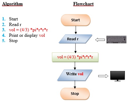
Q2 . Write a program the converts the input Celsius degree into its equivalent Fahrenheit degree. Use the formula: F = (9/5) *C+32.
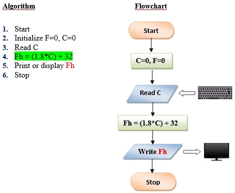
Q3 . Write a program that converts the input dollar to its peso exchange rate equivalent. Assume that the present exchange rate is 51.50 pesos against the dollar. Then display the peso equivalent exchange rate.
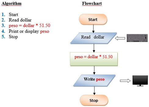
Q4 . Write a program that converts an input inch(es) into its equivalent centimeters. Take note that one inch is equivalent to 2.54cms.
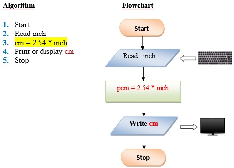
Q5 . Write a program that exchanges the value of two variables: x and y. The output must be: the value of variable y will become the value of variable x, and vice versa.
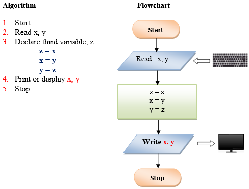
Q6 . Design a program to find the circumference of a circle. Use the formula: C=2πr, where π is approximately equivalent 3.1416.
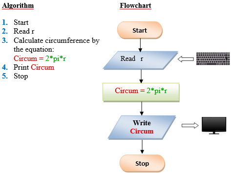
Q7 . Write a program that takes as input the purchase price of an item (P), its expected number of years of service (Y) and its expected salvage value (S). Then outputs the yearly depreciation for the item (D). Use the formula: D = (P – S) Y.
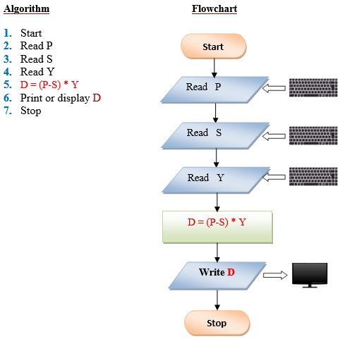
Q8 . Swapping of 2 variables without using temporary (or 3 rd variable).
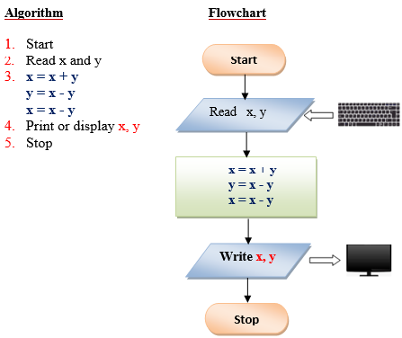
Q9 . Determine the most economical quantity to be stocked for each product that a manufacturing company has in its inventory: This quantity, called economic order quantity (EOQ) is calculated as follows: EOQ=2rs/1 where: R= total yearly production requirement S=set up cost per order I=inventory carrying cost per unit.
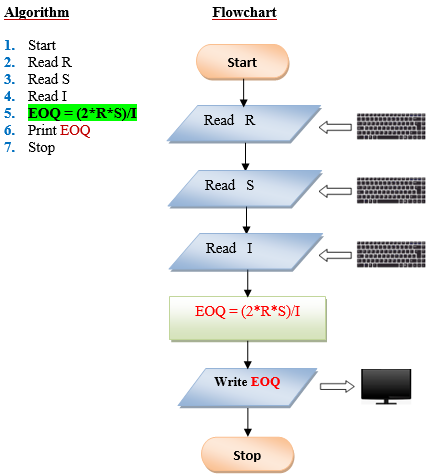
Q10 . Write a program to compute the radius of a circle. Derive your formula from the given equation: A=πr², then display the output.
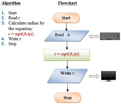
- ← Solved Assignment Problems in Java (with Algorithm and Flowchart)
- Simple if statement in C →
Gopal Krishna
Hey Engineers, welcome to the award-winning blog,Engineers Tutor. I'm Gopal Krishna. a professional engineer & blogger from Andhra Pradesh, India. Notes and Video Materials for Engineering in Electronics, Communications and Computer Science subjects are added. "A blog to support Electronics, Electrical communication and computer students".

You May Also Like
Programming constructs, linear search algorithm, examples of algorithms and flow charts – with java programs, leave a reply cancel reply.
Your email address will not be published. Required fields are marked *
Tutorial - Building a Flowchart
This brief tutorial will guide you through building and executing a simple flowchart.
We would like a flowchart that asks the user for a number, and then counts down to zero (displaying each number to the MasterConsole ).
1. Start Raptor.
2. Add a Input symbol to the flowchart by left-clicking once on the Input symbol and then adding it between Start and End. }}--> }}-->Double click to add the prompt "Enter a number:" and use the variable name Count.

3. Next, add a Loop structure and edit its expression to
}}--> }}-->Count < 0
4. Add an Output symbol to output the variable Count to the MasterConsole.

5. Add an Assignment symbol to decrement the value of Count. }}--> }}-->Edit the statement to
}}--> }}-->Count = Count - 1

IMAGES
VIDEO
COMMENTS
In the New Diagram window, select Flowchart and click Next. You can start from an empty diagram or start from a flowchart template or flowchart example provided. Let's start from a blank diagram. Select Blank and click Next. Enter the name of the flowchart and click OK. Let's start by creating a Start symbol.
Flowchart Symbol. Name. Description. Process symbol. Also known as an "Action Symbol," this shape represents a process, action, or function. It's the most widely-used symbol in flowcharting. Start/End symbol. Also known as the "Terminator Symbol," this symbol represents the start points, end points, and potential outcomes of a path.
30+ Flowchart Examples (With Guide, Tips and Templates) One tried-and-true visual format for dissecting complicated processes is the flowchart. You've probably seen all types of these, from humorous ones to those used in technical fields such as computer programming and engineering. Flowcharts are diagrams that graphically represent a step-by ...
Organize the flow. Determine the order of the steps in the process and the different paths that can be taken. This will help you organize the flow of the flowchart. Use Creately's Plus Create to add the next shape and the connector in a single click. 4.
Here are the five most common shapes used in a flowchart. Oval (Terminal symbol) Rectangle (Process symbol) Arrow (Arrow Symbol) Diamond (Decision symbol) Parallelogram (Input/Output symbol) You can see most of these shapes in the following flowchart examples: CREATE THIS TEMPLATE.
In the most basic sense, flowchart or flow chart, is a type of diagram that describe processes. . Flowchart represents information or processes as boxes, lines, and text. The boxes represent activities, the lines (or flowlines ) represent the workflow that connects them, and the text represents what happens at each activity.
A flowchart is a type of diagram that represents an algorithm, workflow or process. The flowchart shows the steps as boxes of various kinds, and their order by connecting the boxes with arrows. ... The rectangle depicts a process such as a mathematical computation, or a variable assignment. Decision. The diamond is used to represent the true ...
These basic flowchart symbols appear in most diagrams. Once you know these, you can read most flowcharts. 1. Terminator symbol. Meaning: the start or end of a process. An oval symbol marks the first and last steps of a process. You can include "start" or "end" in the oval to highlight their order.
Step #1: Know the purpose of your flowchart. Step #2: Start with a template. Step #3: Add shapes and symbols. Step #4: Connect your shapes with lines and arrows. Step #5: Split paths or add decisions. Step #6: Customize your flowchart's appearance. Step #7: Download or share your flowchart.
Viewers like lightweight and clear schemes. 2. Make it Clear and Simple. The main goal of every flowchart is the simplification of data perception. So, if yours is too complex and viewers can't get what's going on, your flow chart design should be reworked or enhanced. Don't overload it with texts or images.
If more than the most basic flowchart symbols appear in your diagram, it is good practice to include a legend or symbol key. Most flowcharts should be built using only the Start/End and Action or Process symbols and should follow a very basic set of best practices. Sticking with these two primary flowchart symbols is the best way to ensure that ...
A flowchart is a graphical representation of an algorithm.it should follow some rules while creating a flowchart. Rule 1: Flowchart opening statement must be 'start' keyword. Rule 2: Flowchart ending statement must be 'end' keyword. Rule 3: All symbols in the flowchart must be connected with an arrow line.
A flowchart is defined as a symbolic or a graphical representation of an algorithm that uses different standard symbols. Flowchart Symbols: Guidelines for drawing a flowchart. The Title for every flowchart is compulsory. There must be START and END point for every flowchart. The symbols used in flowchart should have only one entry point on the top.
Algorithms. 1. Introduction. In this tutorial, we'll study how to represent relevant programming structures into a flowchart, thus exploring how to map an algorithm to a flowchart and vice-versa. First, we'll understand why using pseudocode and flowcharts to design an algorithm before actually implementing it with a specific programming ...
Go to the online draw.io editor. Select Device to save your flow chart to your device. Note: You can select another location to store your diagram file, but you may be prompted to grant the editor permission if you select a cloud storage platform. Click on Create New Diagram . In the template manager, enter a filename for your flow chart ...
q = myFunction (x,y); Use a Predefined Process symbol, if myFunction is formally defined elsewhere; otherwise use a Process symbol. Thank you for the detailed answer. Actually, this is an assignment statement involving a defined subroutine call. Although, assignment statements are usually shown with Process symbol in flowcharts, it seems more ...
Examples of flowcharts in programming. 1. Add two numbers entered by the user. Flowchart to add two numbers. 2. Find the largest among three different numbers entered by the user. Flowchart to find the largest among three numbers. 3. Find all the roots of a quadratic equation ax2+bx+c=0.
In RAPTOR, there are a few main functions to be used in creating a flowchart. Those functions are: Assignment: Used to change the value of a variable. The right hand side of the assignment is ...
Flowchart Maker and Online Diagram Software. draw.io is free online diagram software. You can use it as a flowchart maker, network diagram software, to create UML online, as an ER diagram tool, to design database schema, to build BPMN online, as a circuit diagram maker, and more. draw.io can import .vsdx, Gliffy™ and Lucidchart™ files .
Program. An algorithm is defined as sequence of steps to solve a problem (task). A flowchart is pictorial (graphical) representation of an algorithm. Set of instructions. Instruction is a command to the computer to do some task. Algorithm can also be defined as a plan to solve a problem and represents its logic. A picture is worth of 1000 words.
2. Add a Input symbol to the flowchart by left-clicking once on the Input symbol and then adding it between Start and End. Double click to add the prompt "Enter a number:" and use the variable name Count. 3. Next, add a Loop structure and edit its expression to. Count < 0. 4. Add an Output symbol to output the variable Count to the MasterConsole.
How to assign values to variables.
1. ASSIGNMENT ON DIAGRAM AND FLOWCHART SUBMITED BY-KRISHNA CHANDRA SAGAR 1S SEMESTER ROLL NO-MBA 1910. 2. DIAGRAM-A diagram is a two-dimensional geometric symbolic representation of information according to some visualization technique. Sometimes, the technique uses a three-dimensional visualization which is then projected onto the two ...